The Mechanical Subcooler controller was designed as a simple and eco-
nomical means of controlling an Electric Expansion Valve on almost any
mechanical subcooling system. True pressure and temperature superheat
ensures accurate control and safety. All components (valves, controller,
sensors) must be supplied by Sporlan to assure compatibility and proper
operation. Please see Tables 3 and 4 on page 4 for correct part numbers.
Pressure-temperature superheat control for one of four common refriger-
ants may be selected. Controllers can be ordered configured for R-22,
R-404A, R-422D, and R-507. The refrigerant type can be changed in the
field by use of the optional Panel Display, part number 958737. Onboard
readouts show actual leaving liquid temperature, superheat, suction pres-
sure, and liquid temperature set point. Two push buttons are provided
on the board, to change the liquid temperature set point, as well as open,
close, or position the valve.
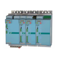
As illustrated, the controller is provided with hardware and input/output
connections for a number of user specified purposes. See below:
•Onevalvecontrol
•Onepressureinput(transducersuppliedbySporlanorCustomer)
•Onedigitalinput(fromexternalswitchesorrelays)
•Twotemperatureinputs(Sporlansuppliedsurfaceorairsensors)
•Optionalbatterybackupforonboardclockandfail-safevalveclosure
•TwodigitLEDreadout
•Green&redLEDstatusindicators
•Twopushbuttonsforsettingsuperheat,etc.
•PanelDisplayjack
INSTALLATION
When handling the boards, electrostatic protection procedures
should be followed. The person installing the controller should be
grounded through a ground strap. If ground straps and other ESD
protection are not available, handle the board only by the edges
of the board. Another fairly safe place to hold the board is by the
battery holders. DO NOT TOUCH ANY COMPONENTS ON THE
BOARD EXCEPT THE BATTERY HOLDER OR RELAYS.
1. The board should be mounted in a dry, protected environment using
the5mountingholes.Makesurenoneoftheprintedcircuitpathsor
components are touching the metal panel or any thing else conductive.
2. Ifonlyonevalveisused,connectionsaretobemadetoterminalblock
closest to display readout and push buttons PB1 and PB2.
3. Controllers are configured for pressure temperature superheat.
4. Connect suction temperature sensor to TS2. The sensor is not polar-
ized. The sensor should be mounted to the suction line after the evapo-
rator using the furnished clamps.
5. Connect leaving liquid temperature sensor to TS1. The sensor is not
polarized.
6. The pressure transducer should be mounted on the suction line near
the temperature sensor location. Sporlan has supplied transducer
cables with two combinations of wire colors. Connect the wires to the
terminals on the board in accordance with Table 1 below. If the cable
issplicedinthefieldtoextenditslength,caremustbetakentoassure
that the new wire is properly connected to the board.
7. DI1 is a digital input used to close the valve. A short or closed contact
from an external relay will close the valve for pump down.
8. Powerisconnectedtotheterminalmarked24VAC.Powerrequirements
are 24 volts AC at 40 VA. For protection from electrical transients,
connect one MOV varistor between one leg of the input voltage of the
24 VAC transformer and earth ground. See Figure 4. Connect a second
MOV varistor between the other leg of the input voltage of the 24 VAC
transformer to earth ground. Two MOV varistors are included with the
controller.
OPERATION
When first powered up the numeric display will show actual leaving liquid
temperature.
1. Whenpowerisapplied,thegreenLEDwillbeonconstantlyandthe
2 digit display will show the leaving liquid temperature as read by the
controller.TheredLEDisthenegativesign.IftheredLEDisoff,the
2digitdisplayreadingisbetween0to99°F.IftheredLEDison,the
2 digit display reading is between -50 and 0°F. Pressing button PB1
at any time will cause the 2 digit display to show the leaving liquid
temperature as read by the controller.
2. Pressing button PB2 at any time will cause the 2 digit display to
show the superheat as read by the controller. The 2 digit display read-
ing is between 0 to 99°F. Pressing button PB2 at any time will cause
the 2 digit display to show the superheat as read by the controller.
3. Pressing buttons PB1 and PB2 simultaneously at any time will cause
the 2 digit display to show the suction pressure as read by the control-
ler.TheredLEDisthe100’sdigit.IftheredLEDisoff,the2digit
displayreadingisbetween0to99PSIG.IftheredLEDison,the2
digitdisplayreadingisbetween100and153PSIG.
4. Whenever the controller is in pumpdown or defrost, the 2 digit will
display dF.
5. Pressing and holding buttons PB1 and PB2 simultaneously until the
greenLEDstartsblinkingwillcausethe2digitdisplaytoshowthe
leavingliquidtemperaturesetpoint.WhilethegreenLEDisblink-
ing, pressing PB1 will increment the set point by 1°F. While the
One Digital Input
One Pressure
Input
One Valve Input
Two Temperature
Inputs
Two Set Point
Pushbuttons
Holders for
Optional Fail
Safe Batteries
Two Digit
LED Display
Green
Status LED
Red Status LED
Panel Display Jack
24 Volt AC
50/60 Hz.
40 VA Input
Figure 1
Terminals for Valve 1 shown.
SUBCOOL-O-MATIC
MECHANICAL SUBCOOLER CONTROLLER
Installation and Servicing Instructions
CONTROLLER
TERMINAL
OLD PIGTAIL
LEADS
NEW HERMETIC
CABLE
1+ or 2+ Red Black
1- or 2- Black Green
1S or 2S Green White
Table 1