PWSA 20-Li A1
■ 30 │ GB│MT
RISK OF INJURY
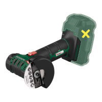
► Make sure that the blade guard
is fitted
at least at the same angle as the additional
handle (see fig. B). Otherwise, you could
injure yourself on the roughing disc or cutting
disc.
♦ Open the clamping lever
.
♦ Place the blade guard with the coding pin
in the coding groove .
♦ Turn the blade guard to the required position
(working position). The closed side of the blade
guard must always be toward the operator.
♦ Close the clamping lever
to clamp the blade
guard into position. If necessary, the clamping
force of the lock can be changed by loosening
or tightening the adjusting nut . Ensure that
the blade guard sits firmly on the neck of the
spindle.
Fitting the additional handle
ATTENTION!
► For safety reasons, this appliance may only
be used with the additional handle
.
Failure to do this can lead to serious injury.
The additional handle can be screwed
onto the left or the right depending on the job
at hand.
Fitting/changing the roughing/
cutting disc
Always wear protective gloves when changing
cutting/rough grinding discs.
Pay attention to the dimensions of the roughing/
cutting disc. The diameter of the hole must fit the
mounting flange
without any play. Do not use
a reducer or adapter.
NOTE
► Use only discs which are free of dirt.
■ Use only grinding discs whose permissible
speed rating is at least as high as that on the
type plate on the power tool.
■ RISK OF INJURY! Press the spindle locking
button
only when the mounting spindle is
at a complete standstill.
♦ Press the spindle locking button
to lock the
motor.
♦ Undo the clamping nut
using the two-hole
mounting spanner (see fig D).
♦ Place the rough grinding or cutting disc with
the label side towards the appliance on the
mounting flange
.
♦ Then replace the clamping nut
with the
raised side facing up on the mounting spindle .
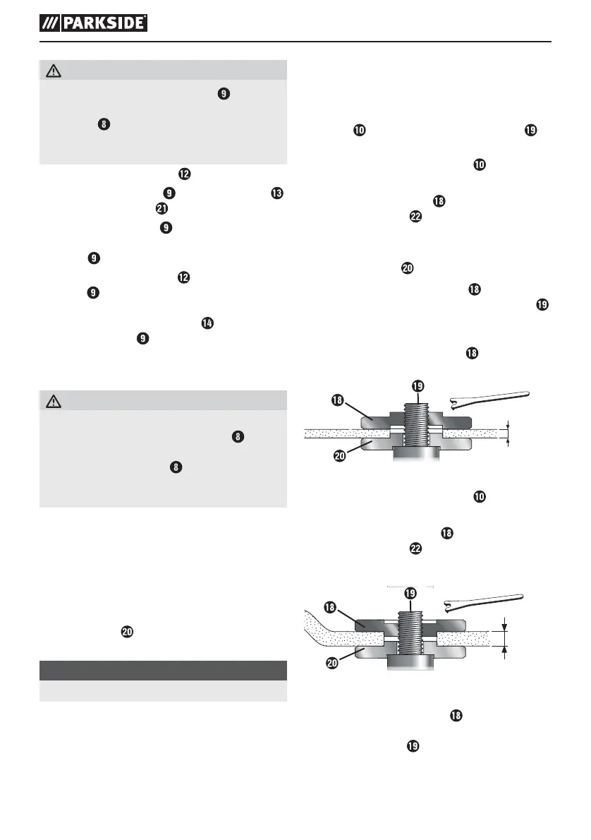
With thin grinding discs (see fig. 1):
♦ The collar of the clamping nut
faces upwards
so that a thin grinding disc can be fitted safely.
≤ 3,2 mm
Fig. 1
♦ Press the spindle locking button
to lock the
motor.
♦ Tighten the clamping nut
using the two-hole
mounting spanner .
With thick grinding discs (see fig. 2):
> 3,2 mm
Fig. 2
The collar of the clamping nut
faces downwards
so that the grinding disc can be fitted securely onto
the mounting spindle .
 Loading...