Do you have a question about the Peavey XR 800 and is the answer not in the manual?
| Brand | Peavey |
|---|---|
| Model | XR 800 |
| Category | Music Mixer |
| Language | English |
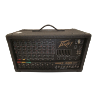
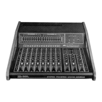
Introduces the XR-800/XR-1200 as a comprehensive, state-of-the-art powered mixing console with advanced features.
Explains how to adjust input gain for optimal signal level, headroom, and signal-to-noise ratio.
Describes the use of two separate monitor mixes (A & B) for stage monitoring.
Details the LOW, MID, and HIGH active EQ controls for frequency response adjustment.
Controls the amount of signal sent to internal reverb or external effects devices.
Manages channel output assignment to Main A or Main B for stereo imaging or sound reinforcement.
Sets the overall output level for each channel feeding into the main summing busses.
Combines A & B main signals for monaural output and house level control.
Blends effects return signals into the Monitor A mix.
Regulates the amount of signal from the effects return feeding the effects pan control.
Allows blending of the effects return into Main A or B outputs.
Controls the master output levels for the two independent monitor buses (A & B).
Control the overall signal levels for the Main A and B outputs to amplifiers/EQs.
Blends reverberation into the Monitor A mixing bus.
Manages the level and panning of the delayed (reverb) signal into main outputs.
Blends reverberation into the Monitor B mixing bus.
Final control for effects send output level and internal reverb system signal.
Adjusts the overall signal summed from PFL channels, overriding normal headphone level.
Controls headphone output level and describes the standard stereo headphone jack.
Details the two 9-band graphic equalizers for tone coloration and room equalization.
Explains DDT (Distortion Detection Technique) compression for preventing clipping and maximizing amp output.
Describes balanced/unbalanced inputs and effects loop send/return jacks for each channel.
Details preamp outputs for mains, monitors, sum, and effects output with level control.
Describes patching jacks for integrating graphic equalizers elsewhere in the system.
Allows patching external signals directly into power amp inputs, bypassing EQ.
Jack for a footswitch to remotely defeat the reverb function.
Auxiliary input for completing the effects loop or mixing external devices.
Bypasses mains A/B and master section to go directly to the sum fader.
Line-level inputs for injecting signals into internal mixing busses (Main, Monitor, Effects).
Output jacks for connecting speaker systems to the internal power amplifiers.
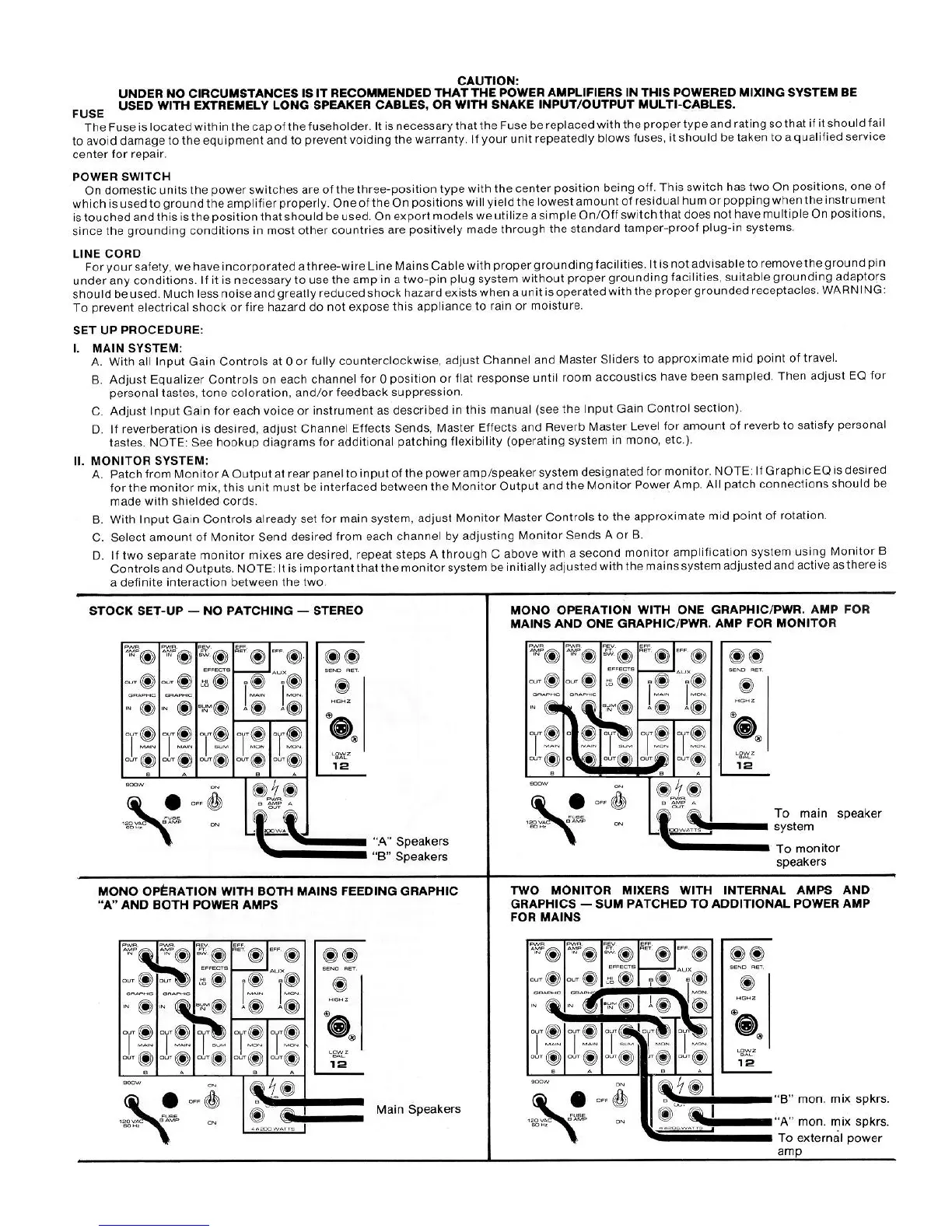
Advises using short, thick speaker cables for maximum power and performance.
Emphasizes using the correct fuse type and rating to prevent damage and voiding warranty.
Explains the three-position power switch and optimal grounding position for domestic units.
Stresses the importance of the three-wire line cord and proper grounding for safety and noise reduction.
Guides setting input gain, channel/master sliders, and equalization for the main system.
Details patching monitor outputs and adjusting monitor send levels for stage monitoring.
Illustrates a basic stereo setup without external patching.
Shows mono operation using one graphic EQ and power amp for mains and one for monitors.
Depicts mono operation where both mains feed one graphic EQ and both power amps.
Illustrates using two monitor mixers with graphics, summing to an additional power amp for mains.
Diagram showing bi-amplification setup with a PL-SP-1 module for horns and bass speakers.
Explains patching effects units into the mixer's send/return loop.
Illustrates connecting two XR mixers for expanded capability.
Shows how to connect the mixer outputs to a tape deck for stereo or mono recording.
Lists the main features and capabilities of the XR-800/XR-1200 mixers.
Details the unbalanced auxiliary and high impedance inputs for master sections.
Describes the low impedance unbalanced send line output for each channel.
Lists the low impedance unbalanced outputs for mains, monitors, sum, and effects.
Specifies the parallel output jacks for connecting speakers to power amps.
Provides detailed specifications for microphone input impedance and levels.
Gives specifications for high impedance line inputs, including levels and impedance.
Details specifications for channel returns, auxiliary, and graphic inputs.
Provides specifications for the effects return input, including levels and impedance.
Details specifications for various master outputs, including nominal and maximum levels.
Provides specifications for the low level unbalanced effects output.
Details specifications for the headphone output, including load impedance and max power.
Defines the conditions under which the subsequent performance specifications were measured.
Specifies the frequency response across different input/output combinations.
Provides signal-to-noise ratios for high Z line inputs and low Z mic inputs.
Details THD (Total Harmonic Distortion) for various input/output combinations.
Specifies the frequency points and Q factor for the graphic equalizers.
Reports crosstalk levels between channels at 1 KHz.
Lists the maximum gain achievable through various controls and stages.
Defines the dB range covered by the LED level meters for mains and monitors.
Specifies the dynamic range provided by the DDT compression system.
Reports the maximum THD with DDT compression at overload conditions.
Details the shelving and peak/notch EQ specifications for each channel on the XR-800.
Provides specifications for the XR-800's power amplifier section, including frequency response and power output.
States the rated power output per channel into a 4-ohm load.
Lists the power output in RMS at clipping point for various impedances.
Specifies the THD for the power amplifier section across different power levels and impedances.
Details the IM distortion for the power amplifier section.
Reports the hum and noise level relative to the amplifier's rated power.
Provides the slew rate for the power amplifier section.
Specifies the damping factor of the power amplifier.
Indicates the input signal level required to achieve rated power output.
States the input impedance of the power amplifier section.
Lists the power consumption in watts for the unit.
Details the shelving, peak/notch, and overall EQ specs for XR-1200 channels.
Provides specifications for the XR-1200's power amplifier section, including frequency response and power output.
States the rated power output per channel into a 4-ohm load for the XR-1200.
Lists the power output in RMS at clipping point for various impedances on the XR-1200.
Specifies the THD for the XR-1200 power amplifier section.
Reports the hum and noise level relative to the XR-1200's rated power.
Provides the slew rate for the XR-1200 power amplifier section.
Specifies the damping factor of the XR-1200 power amplifier.
Indicates the input signal level required for rated power output on the XR-1200.
States the input impedance of the XR-1200 power amplifier section.
Lists the power consumption in watts for the XR-1200.
Illustrates the internal signal path from input to output for each channel and the master section.
Warns about exposure to high noise levels and the risk of permanent hearing loss.
Lists crucial safety and operating instructions regarding usage, environment, and servicing.