Product information10
Copyright © 2013 Pico Technology Limited. All rights reserved.ps2200a.en r1
3.5
Connections
3.5.1
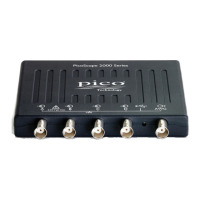
Connector diagrams
A. Input channel A
B. Input channel B
C. AWG output
D. LED: shows when the oscilloscope is sampling data
E. USB port
3.5.2
Signal inputs
The PicoScope 2200A Series oscilloscopes have BNC oscilloscope connectors. The
inputs have an impedance of 1 M , so they are compatible with all standard scope
probes including x10 attenuated types.
3.5.3
Compensating probes
We recommend that you compensate each oscilloscope probe before using it with your
PicoScope. Compensation instructions specific to the probe are included in the leaflet
supplied with the probe.
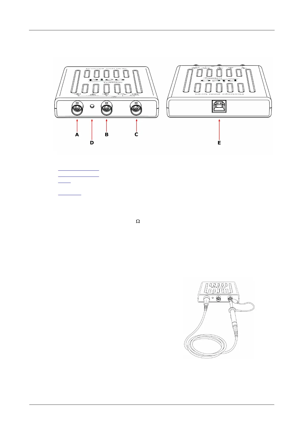
Connecting a probe for compensation
1. Connect your probe to the signal generator
output as shown on the right.
2. Run the PicoScope software.
3. Click the AWG button and set the AWG to
generate a 1 kHz 1 volt square wave.
4. Follow the compensation (or 'trimming')
instructions in the probe leaflet.
 Loading...