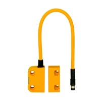
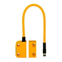
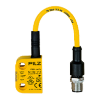
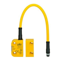
The PSEN ma1.4a-51 is a magnetic safety switch designed for safety gate monitoring, offering reliable and robust operation in industrial environments. It is intended for use in conjunction with specific actuators and evaluation devices to ensure functional safety in accordance with relevant standards.
Function Description
The primary safety function of the PSEN ma1.4a-51 is to open its safety contacts when the associated actuator is removed beyond the assured release distance (sar) or when the actuator is not detected. This ensures that a hazardous situation, such as an open safety gate, is immediately recognized and appropriate safety measures are initiated.
The safety switch operates magnetically and features a coded actuator, preventing simple manipulation. When the actuator is within the response range (indicating a closed safety gate), both the two safety contacts (normally open - N/O) and the one auxiliary contact (N/O) on the safety switch will close, and an integrated LED will illuminate to indicate the switch status.
The PSEN ma1.4a-51 must be operated with either the PSEN ma1.4-03 actuator (with an assured operating distance of 3 mm) or the PSEN ma1.4-10 actuator (with an assured operating distance of 10 mm). It also requires connection to a suitable evaluation device. Pilz offers certified evaluation devices such as PNOZelog, PNOZpower, and PNOZsigma for safety gate monitoring. Other compatible evaluation devices must meet specific criteria, including 2-channel operation with feasibility monitoring, open circuit monitoring of the safety switch, and inputs/outputs compliant with IEC 61131, Type 3. The technical data of the evaluation device must also align with the requirements of the PSEN ma1.4a-51.
For evaluation devices with DC supply voltage, an overall cable resistance of ≥ 15 Ohms per channel is required, while for AC supply voltage, it's ≥ 25 Ohms per channel. The maximum switching current for the safety contacts of the PSEN ma1.4a-51 must always be adhered to. A partial operation lock ensures that outputs at the evaluation device are only switched on again when both reed contacts at the safety switch have been opened and closed.
Important Technical Specifications
General:
- Certifications: CE, EAC, TÜV, UKCA, cULus Listed.
- Sensor's mode of operation: Magnetic.
- Coding level in accordance with EN ISO 14119: Low.
- Design in accordance with EN ISO 14119: 4.
- Classification in accordance with EN 60947-5-3: PDDB.
Electrical Data:
- Supply voltage: 24 VDC.
- Voltage tolerance: -20 %/+20 %.
- Max. current: 200 mA.
- Max. switching frequency: 1 Hz.
- Lowest operating current (Im): 1 mA.
- Switching voltage: 24 V.
- Internal resistance: 10 Ohm.
- Max. switching current, safety contacts: 0.2 A.
- Max. breaking capacity, safety contacts: 5 W.
- Max. switching current, auxiliary contacts: 10 mA.
Times:
- Reaction time (actuator removed): 2 ms.
Environmental Data:
- Ambient temperature range: -10 to 55 °C.
- Climatic suitability (IEC 60068-2-30): Humidity 93 % r. h. at 40 °C.
- Max. operating height above sea level: 2000 m.
- EMC: EN 60947-5-3.
- Vibration (EN 60947-5-2): Frequency 10 - 55 Hz, Amplitude 1 mm.
- Shock stress: Acceleration 30g, Duration 11 ms.
- Airgap creepage: 3.
- Pollution degree: 3.
- Rated insulation voltage: 250 V.
- Rated impulse withstand voltage: 4 kV.
- Protection type: IP67, IP69.
Operating Distances:
- PSEN ma1.4-03mm actuator:
- Assured operating distance Sao: 3 mm.
- Min. operating distance Somin: 0.0 mm.
- Typical operating distance So: 3.5 mm.
- Assured release distance Sar: 12 mm.
- Typical release distance Sr: 6 mm.
- PSEN ma1.4-10mm actuator:
- Assured operating distance Sao: 10 mm.
- Min. operating distance Somin: 0.0 mm.
- Typical operating distance So: 12.5 mm.
- Assured release distance Sar: 22 mm.
- Typical release distance Sr: 16 mm.
- Repetition accuracy switching distances: 6 %.
- Min. distance between safety switches: 50 mm.
Mechanical Data:
- Connection type: 5 m cable, LiY11Y 8 x 0.14 mm2.
- Material (Top): PBT.
- Max. torque setting: Safety switch 0.8 Nm, Actuator 1 0.8 Nm.
- Dimensions (Safety switch/Actuator): Height 37 mm, Width 26.4 mm (switch) / 18 mm (actuator), Depth 18 mm.
- Weight: Safety switch 220 g, Actuator 16 g (PSEN ma1.4-03mm) / 18 g (PSEN ma1.4-10mm), Total 236 g / 238 g.
Safety Characteristic Data (B10d and TM [year] in accordance with EN ISO 13849-1:2015 and EN 62061):
- Sensor, 2-ch, ≤ 5 mA: B10d 40,000,000, TM 20.
- Sensor, 2-ch, 5mA < I ≤ 60 mA: B10d 11,000,000, TM 20.
- Sensor, 2-ch, > 60 mA: B10d 3,000,000, TM 20.
Usage Features
The PSEN ma1.4a-51 is designed for flexible installation and reliable operation.
- Installation: The unit can be installed in any position, but the safety switch and actuator must be positioned opposite each other in parallel. To avoid changes in operating distances, it is recommended not to install the safety switch and actuator on ferromagnetic material.
- Mounting: The safety switch and actuator must be secured against changes in position, preferably using screws and nuts made of non-magnetic material (e.g., brass or stainless steel). The fastening elements should be prevented from self-loosening.
- Alignment: The inscribed area on the actuator (sensing face) should face the sensor. Alignment errors of the guard must not adversely affect the safety function.
- Operating Distances: The stated operating distances are valid when the switch and actuator are installed according to specifications. Deviations may occur with other arrangements. The maximum permitted lateral and vertical offset must be considered.
- Environmental Considerations: The switch and actuator should be kept away from iron swarf and strong magnetic fields. They must not be exposed to heavy shock or vibration and should not be used as an end stop.
- Manipulation Protection: Measures must be taken to prevent the circumvention of the safety switch in a reasonably foreseeable manner. The actuator should be protected from unauthorized removal and contamination. If substitute actuators are used, they must be installed as described in the manual, and original actuators must be destroyed.
- Auxiliary Contact with LED: The auxiliary contact and LED indicate the status of the safety contacts. The LED lights up when the actuator is in the response range (safety contacts closed) and is off when the actuator is removed (safety contacts open). The auxiliary contact with LED may only be operated with a supply voltage of up to 24 VDC with PNOZ X units and is not to be used for safety circuits or connected in series with PNOZ X, PNOZelog, and PNOZmulti units.
- EMC Compliance: The product is designed for industrial environments. If installed in other environments, measures should be taken to comply with applicable standards and directives regarding interference.
Maintenance Features
- Periodic Test: A monthly function test on the safety switch and actuator is required. This test must always be performed with a connected evaluation device and by qualified personnel to ensure the safety function is maintained.
- Assured Operating and Release Distances: The assured operating distance (Sao) and assured release distance (Sar) must be tested under real conditions during commissioning and periodic checks.
- Non-flush Installation: If the safety switch is installed non-flush within electrically or magnetically conductive material, the value for the assured release distance (Sar) can change and must be checked.
- Documentation: The operating manual should be retained for future reference, and personnel should be familiar with its contents before installation and commissioning.