A-209R, A-209
27
6. ADJUSTMENT
6.1 IDLE CURRENT ADJUSTMENT
¶ CAUTION : Heatsinks’ (Q323–Q326) DC level is equal to +B or -B.
Don’t touch them or you will be electric shocked.
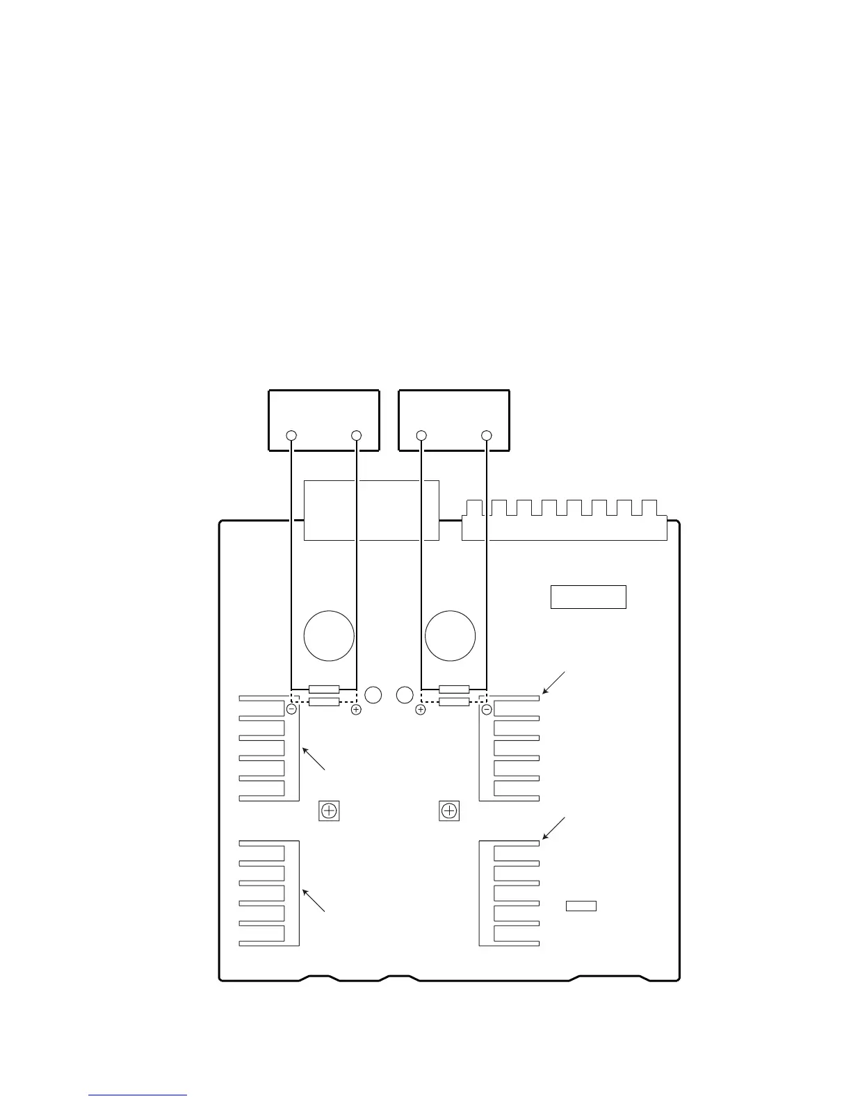
1. Connect the measuring instrument as shown in Fig.6-1. (R373 or R374)
2. Turn the POWER switch to ON.
3. Adjust VR301 (VR302) so that the voltage between both sides of R373 (R374) becomes 10mV ± 1mV.
4. Ages for 5 minutes.
5. Adjust VR301 (VR302) so that the voltage between both sides of R373 (R374) becomes 11mV ± 1mV.
VR301 VR302
R375 R376
R373 R374
Heat Sink
CN202
AF ASSY
DC Voltmeter DC Voltmeter
SIDE A
Heat Sink
Heat Sink
Heat Sink
Fig.6-1 Adjustment Method
 Loading...