6.
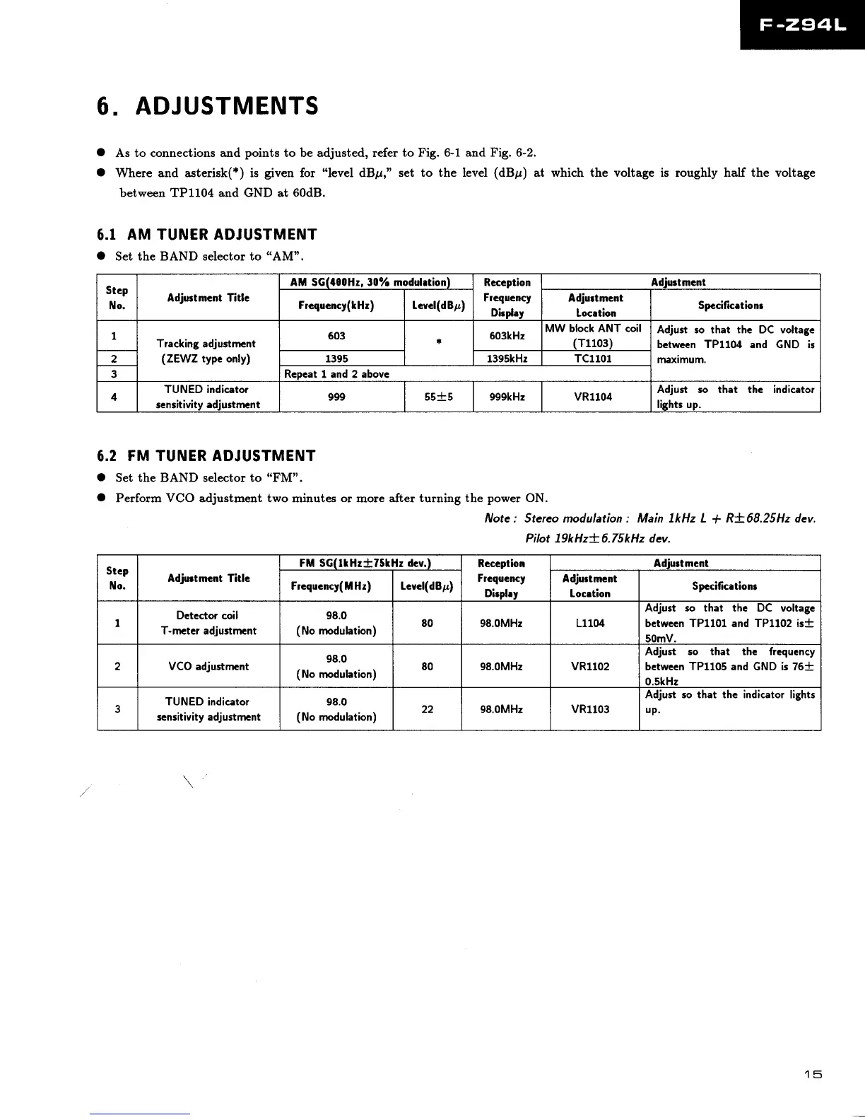
ADJUSTMENTS
O
As
to connections and
points
to be adjusted, refer
to
Fig. 6-1
O
Where and asterisk(*) is
given
for
"level
dBpr,"
set to the
between TP1104 and GND at 60dB.
6.1
AM TUNER ADJUSTMENT
O
Set the BAND selector to
'(AM",
and Fig. 6-2.
level
(dBp)
at which the voltage is roughly half the voltage
Stcp
ilo.
Adjurtmcnt Titlc
AM SG(feOHz, 30olo modslrtion)
Rcccption
Frcqucncy
Dirolrv
Adiuctment
Frcqucncy(lHr) Icvcl(dBp)
Adjurtmcnt
Location
Spccificetionr
1
Tracking adjustment
(ZEWZ
typc only)
603 603kHz
MW block ANT coil
(T1103)
Adjust so that the DC voltagc
bctwccn TP11O4 and
GND is
maximum.
2
1395 1395kHz TC1101
3 Rcpcatland2abovc
4
TUNED indicator
scnsitivitv adiustmcnt
999 55-t-5 999kHz vR1104
Adjust so that thc indicator
lights up.
6.2
FM TUNER ADJUSTMENT
O
Set the BAND selector to
"FM".
O
Perform
VCO
adjustment two minutes
or
more after
turning the
power
ON.
Note : Stereo modulation : Main lkHz L
t
R+68.25H2 dev.
Pilot l9kHzt 6.75kHz dev.
Stcp
No.
Adjortmcot Titlc
FM SG(trHztT5lHr
dcv.)
Rcccption
Frcqocncy
Dirohv
Adiurtment
Frequcncy( ll Hz)
!cvcl(dBp)
Adjuctmcnt
Locrtion
Spccificetionr
I
Detector coil
T-mctcr adjustmcnt
98.0
(No
modulation)
80 98.0MHz L11(X
Adjust so that thc DC voltage
between TP1101 and TP1l02 is-F
50mV.
2 VCO adjustment
98.0
(No
modulation)
80 98.0MHz
vR1102
Adjust so that the frcqucncy
bctwccn TP1105 and GND is 76t
0.5kHz
3
TUNED indicator
scnsitivity adjustmcnt
98.0
(No
modulation)
22 98.0MHz
vR1103
Adjust so that the indicator lights
uP.
15
 Loading...