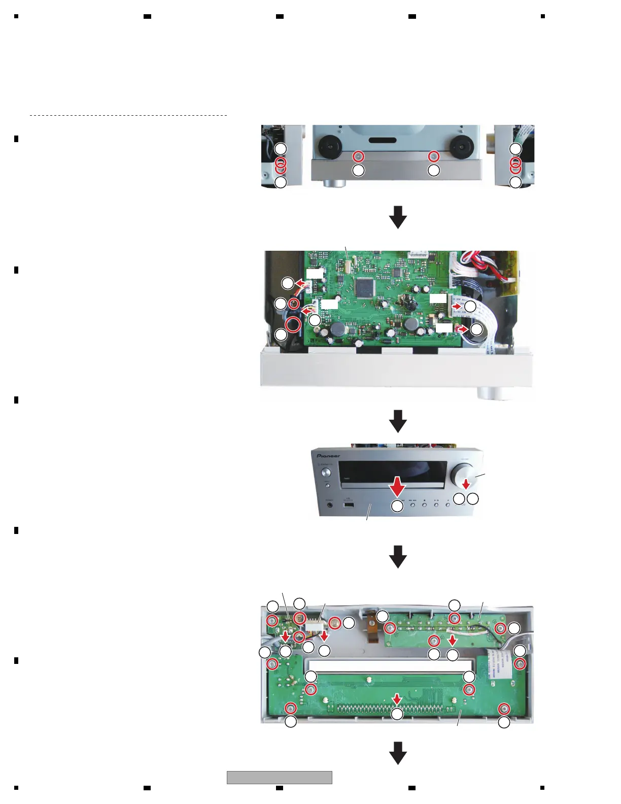
(1) Remove the two screws.
(2) Remove the two screws.
(3) Unhook the two hooks.
[3] Front Panel Section
(1) Remove the top cabinet.
(See procedure "[1] Top Cabinet".)
(4) Disconnect the one flexible cable and three
connectors. (J3, J5, J12, J14)
(5) Release the jumper wires from hook.
(6) Remove the one screw.
(7) Remove the volume knob.
(8) Remove the nut and washers.
(9) Remove the front panel section.
(10) Remove the two screws.
(11) Remove the 12 screws.
(12) Remove the DISPLAY, KEY-SWITCH,
HEADPHONE and USB PCB Assemblies.
9
1 1
22
3 3
Front panel section
DISPLAY PCB Assy
KEY-SWITCH PCB Assy
USB PCB Assy
HEADPHONE PCB Assy
Volume knob
• Bottom view
7 8
6
10
10
11
11
11
11
11
11
11
11
12
12
12
12
11
11
11
11
MAIN PCB Assy
4
J14
J5
J3
J12
4
4
4
5
 Loading...