29
CONCENTRIC VENT INSTALLATION
For new installations of 100,000, 130,000 & 150,000 BTU/hr
units, install 2” Concentric vent kit model KGAVT0501CVT, part
number 100093946. For new installations of 175,000 & 199,000
btu/hr units, install 3” Concentric vent kit model KGAVT0601CVT,
part number 100093947. See Manufacturer’s instructions for
complete installation or call the technical support number listed
on the back cover of this manual. For planning purposes, see
Figures 26 through 30 below for vent terminal specifications.
Note: When terminating concentric vents for additional units (all
models), see “Venting Multiple Units” on Page 30.
Field supplied pipe and ttings are required to complete the
installation.
SAFETY CONSIDERATIONS
Installing and servicing water heating equipment can be hazardous
due to gas and electrical components. Installation and service of
the concentric vent termination requires ability equivalent to that of
a qualied installer or qualied service technician, see Page 8. All
precautions in the literature, on tags, and labels attached to the unit
must be observed.
Follow all safety codes. Wear safety glasses and work gloves.
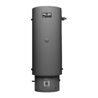
Figure 26. 2 Inch Concentric Vent
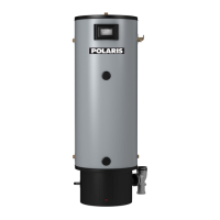
Figure 27. 3 Inch Concentric Vent
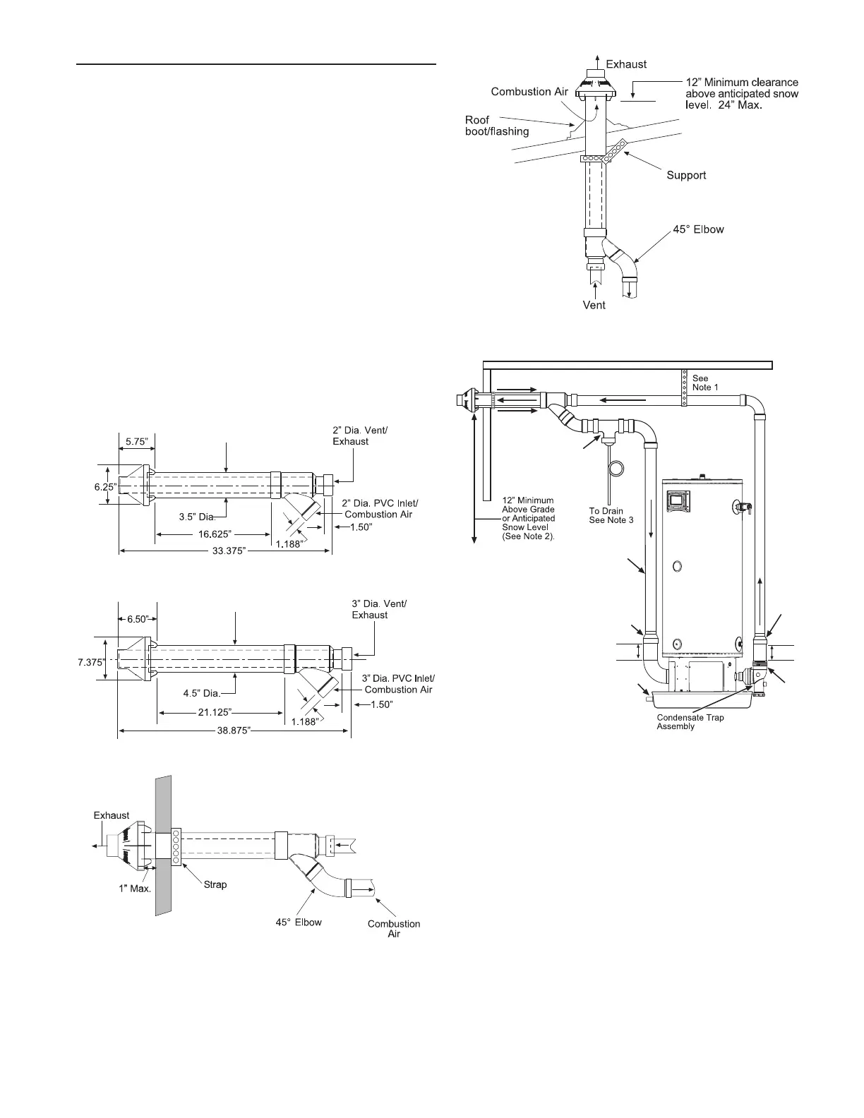
Figure 28. Through the Wall Termination
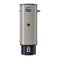
Figure 29. Through the Roof Termination
Tee with
Drain Trap
See Note 4
Trap
NOTES:
1. Support Horizontal Pipe Every Four Feet.
Support Vertical Pipe Every Six Feet.
2. Increase The 12” Minimum Above
Grade To Keep Inlet Opening
Above Anticipated
Snow Levels.
3. Slope All Piping 1/8” Per
Foot
Down Toward The
Water Heater.
4. For units with inputs of
150,000 BTU/hr
and below,
use 2" or 3" pipe. For units
with
inputs of
175,000 BTU/hr
and above,
use only 3" pipe.
5. When venting with 2" pipe, a sufficient
length of 3" pipe (6" minimum) must be
inserted into the exhaust and inlet elbow
assembly before transitioning down to
2" pipe with a 3" x 2" reducer.
See Note
Drain Pan
(Piped to
Adequate
Drain)
3" x 2"
Reducer
Exhaust
Elbow
Assembly
See Note 5
3" x 2"
Reducer
Figure 30. Concentric Vent Piping Installation
 Loading...