volatile memory, high-voltage power supply of the detector, operates the control buttons,
performs all the necessary calculations, self-diagnostics.
The instrument’s operating algorithm ensures continuity of the measurement process,
statistical processing of the measurement results, a prompt adaptation to the variation of
level of the photon radiation dose rate (setting the time of measurement in inverse
dependence on the dose rate) and effective output of the information obtained to the LCD.
The IR-communication channel provides an exchange of information with PC.
The instrument has an internal non-volatile memory that allows the information
accumulation and storage.
Secondary power supply provides transformation of the battery’s voltage 1.5. V into a
stable voltage 3 V necessary for the instrument’s power supply.
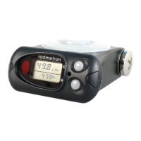
1.4.2 The device is designed as a unit housed in a plastic shock-proof case. General
overview of the instrument and its parts is given in Figure 1.2. Indication elements, positions
1 - 4, are displayed on the LCD (8).
1 – DER analog scale (seven segments) for effective control over radiation situation, analog
scale (four segments) for indication of sound pressure level in search mode.
2 – DER digital panel in DER indication mode, DE in DE indication mode, instrument’s
number, indication of IR communication channel switch on/off in the PC data exchange
mode, indication of search mode switch on/off.
3 – digital panel of the coefficient’s of variation indication in percents in DER indication mode,
DE accumulation time’s indication in thousands of hours (h) in DE indication mode, indication
of production month and year in the instrument’s number indication mode;
4 – digital panel of indication of time of averaging DER values (in seconds) in DER indication
mode, of DE accumulation time in DE indication mode; sound pressure level (from 1 to 4) in
search mode
5 – the LIGHT button for switching on LCD backlight, switching on PC data exchange mode,
entering the set mode and exiting it (see item 2.1.6).
6 – the MODE button for selecting the instrument’s indication mode (DER, DE, the
instrument’s number, PC data exchange);
7 – LED of visual alarm;
8 – LCD;
9 – IR-transceiver window;
10 – detector;
11 – Battery compartment cover.
A direction of calibration and the detector effective center relative to which the factory
calibration is performed are placed at a 15 mm distance from the instrument detector’s
surface (Appendix B).
The total surface density of the walls surrounding the detector is 1 g/cm
2
that provides
the detector shielding from the background beta radiation.
The PM1621M is provided with a clip and may be fasten to the belt. The clip may be
removed using a screwdriver (see Fig.1.3). A carrying pouch is also available as an option.
13
 Loading...