Package 4 - Ceiling Microphones, Ceiling “Can” Style Loudspeakers
Quick Installation Guide
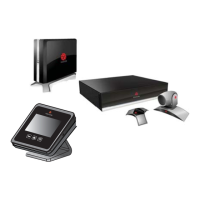
Vortex
®
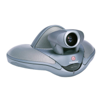
EF2241 - SoundStation VTX 1000
TM
Package
Installed Voice System with Wideband Telephone Connection, Ceiling
Microphones and Ceiling Loudspeakers
Connect. Any Way You Want.
Loudspeaker Installation
Loudspeakers should be installed and connected before powering up the system. Brackets are supplied with the loudspeakers for use with either suspended ceil-
ings or drywall ceilings.
For each loudspeaker:
1. Using the template supplied with the loudspeaker, scribe a cutout hole onto your ceiling surface, then cut out the hole. The hole will be 6.5 inches (165 mm)
in diameter.
2. Insert the backing hardware through the hole. For suspended ceilings, place the C-plate around the hole with the tabs placed so they will line up with the
tile rails. Snap the rails into the two tabs in the C-plate and align the rails so that the ends extend over the T-channel grid on the side of the tile. Secure the
rails onto the C-bracket tabs by inserting a screw through each tab into the rail. For drywall ceilings, the C-bracket can be used by itself to shore up the
ceiling material and to spread out the clamping force from the tab clamps. Insert the C-plate through the cut hole and place it on the back side of the hole.
3. Connect the provided plenum cable to the removable locking connector that is included with the speaker. Strip the wire about 3/16”, insert the bare end of the
wire into the connector and tighten the hold-down screw. Note that you will need to connect the two loudspeakers in parallel; use the Loudspeaker Wiring
directions below.
4. Plug the connector into the connector socket in the speaker’s terminal cup; tighten the strain relief fitting and close the terminal cover.
5. Insert the speaker into the ceiling until the front baffle rim touches the ceiling. Turn the attachment screws to tighten the mounting tabs as follows:
a. FIRST turn 1/2 turn counterclockwise to release the mounting tab from its guide;
b. Then, turn the screw clockwise until tight. Do not overtighten.
6. Press the speaker grille into place until the front of the grille is flush with the rim. Make sure the grille is securely seated.
Complete loudspeaker installation instructions, with diagrams and important safety
information, may be found in the manual accompanying the loudspeakers.
Each loudspeaker provides 120° coverage angle and has a sensitivity of at least 85dB
SPL 1W/1m. As shown at right, assuming a 9 foot (2.7m) ceiling height and a 3.5 foot
(1.1m) ear height, the loudspeaker coverage pattern is a circle with a 19 foot (5.8m)
diameter (drawn from the center of the loudspeaker). A 10 foot (3m) ceiling height
yields a 22 foot (6.7m) radius of coverage. Using the 10 foot (3m) ceiling height as the
worst case scenario and assuming that the Vortex EF2241 amplifier is providing 1W to
the loudspeaker, the listener will hear a signal with 79dB SPL.
Loudspeaker Wiring
The two supplied loudspeakers must be connected in parallel to ensure cor-
rect operation. Using one of the removable terminal blocks for the loud-
speakers, connect the positive (+) wire to the other loudspeaker, along with
a wire from the cable running to the positive (+) terminal of the Vortex
EF2241’s loudspeaker connections, to position #2 on the removable block.
Repeat the process for the negative (-) terminals, using position #3 on the
removable block. You may optionally use the wire nuts provided with your
package instead; connect the two positive (+) wires of the loudspeakers
together with the positive (+) terminal of the Vortex loudspeaker connection,
and repeat the process with the negative (-) wires and Vortex negative (-)
terminal connection.
Please refer to the respective User Guides for each product for detailed installation, warranty and support information.
Copyright © 2004, Polycom, Inc. All Rights Reserved. Polycom, the Polycom logo, and Vortex are registered trademarks and SoundStation VTX 1000, VSX 7000, Conference Composer and InstantDesigner are trade-
marks of Polycom, Inc. in the USA and various countries. All other trademarks are the property of their respective companies. Part #1725-80132-001. Rev 08/04.
+ and - connections to other loud-
speaker
+ and - connections to
Vortex EF2241
Loudspeaker / Microphone Placement
When microphones are installed in the ceiling, special care must be taken to
locate them away from the loudspeakers. With suspended ceilings, try to place
at least two ceiling tiles between loudspeakers and microphones. For drywall
ceilings, try to space the microphones at least 4 feet from loudspeakers. When
using ceiling microphones, it is important to maximize the direct-to-reverberant
sound ratio. Keeping the diagonal talker-to-microphone distance less than 8 feet
(2.4m) will generally produce acceptable ceiling microphone performance. For a 9
foot (2.7m) ceiling height, assuming the talker source is 3.5 feet (1.1m) above the
floor, each ceiling microphone can cover a circular area with a 12 feet (3.7m)
diameter. If the room is acoustically treated, these distances could be increased
while still maintaining an acceptable direct-to-reverberant sound ratio.