Page 6 of 13
©2010 Polycom, Inc. All rights reserved. Polycom and the Polycom logo design and Polycom HDX are registered trademarks of Polycom, Inc.
All other trademarks are the property of their respective owners. Information is subject to change without notice.
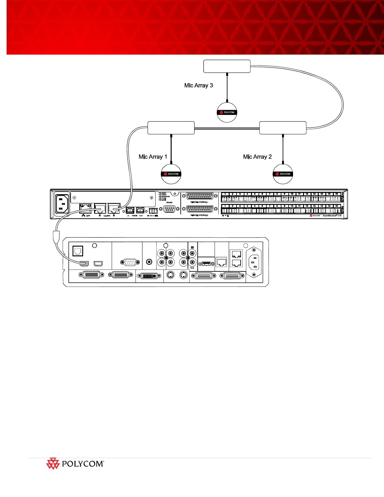
Figure 7. Connecting Polycom Microphone Arrays to the SoundStructure device.
Step 5. Modify the SoundStructure Configuration File
The example configuration file for integrating the SoundStructure with the ATX system is available online
[1]. To upload the example configuration file to the SoundStructure device, follow the instructions in
Section Step 6 Uploading the configuration file in this application note.
To better understand the configuration file settings, the following sections describe the configuration files
in detail.
5.1 Removing Polycom microphone array elements
As described in the ATX system installation manual [2], the microphone arrays should be positioned with
the orientation dot facing the front of the room. When the microphone arrays are oriented properly
(shown in Figure 8), Mic Array 1 is positioned on the room left (camera right), Mic Array 2 positioned on
the room right (camera left), and Mic Array 3 positioned in the center.
The microphone “A” element from each of microphone array has been removed from the example
configuration files because, with proper orientation of the microphone arrays, the “A” elements are