INSTRUCTIONS PL600/PL1000
13
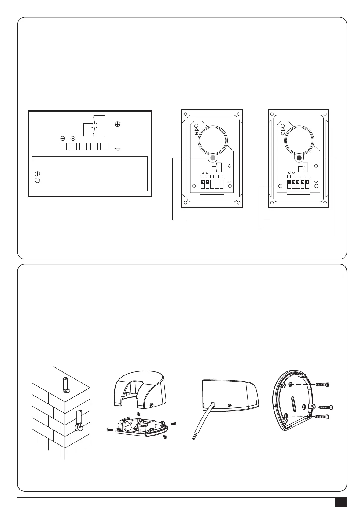
3.3.3 PF-1 Flashing Light
1). Decide the installation position of the flashing light. The flashing light has to be installed near the gate and easy
to be seen by users and passersby. The flashing light can be installed horizontally or vertically. See Figure 3.3.3 (1).
2). Unscrew the four screws on the light base and separate the base with the bottom as shown in Figure 3.3.3 (2).
3.) Connect the wires and penetrate the wires into the hole of the base. See Figure 3.3.3 (3).
4.) Drill the holes in the wall and fix the bottom to the wall by three screws. See Figure 3.3.3 (4).
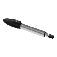
3). Wiring connection:
TX: Connect the (1) and (2) terminals on the transmitter with the terminals GND and PH+ on the PL600/ 1000 PCB.
RX: Connect the (1), (2) and NC terminals on the receiver with the terminals GND、PH+ and PH1 on the
PCB600/1000 PCB. See Figure 3.3.2 (4) Figure 3.3.2 (5).
Figure 3.3.2 (4)
Figure 3.3.3 (1) Figure 3.3.3 (2) Figure 3.3.3 (3) Figure 3.3.3 (4)
Figure 3.3.2 (5)
CA
CC
NA: Normal Open
NC: Normal Close
: DC(+) Input Voltage
: DC(-) Input Voltage
C: Common
CA: AC(12~24)
CC: DC(12~24)
VERT:Vertical
ORIZ:Horizontal
O
R
I
Z
NA NC C
1 2 3 4 5
Power LED: Green
Transmitter
Vertical Adjustment
Horizontal Adjustment
LED:Red(Beam Alignment)
CA
CC
NA NC C
1 2 3 4 5
O
R
I
Z
V
E
R
T
Receiver
CA
CC
NA NC C
1 2 3 4 5
O
R
I
Z
V
E
R
T

 Loading...