INSTRUCTIONS PL600H/PL1000H
10
E
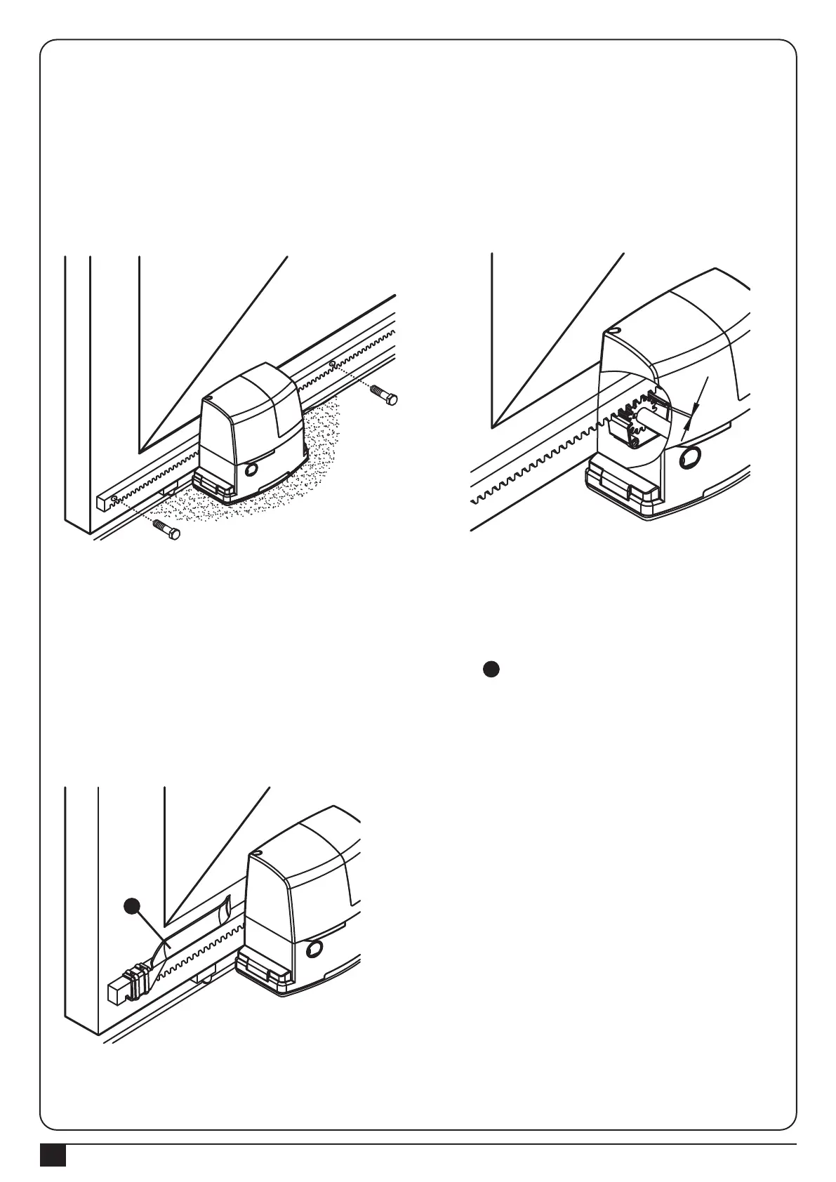
Figure 21
Figure 23
Figure 22
11). Release the gearmotor by using the release key if necessary.
12). Fully open the gate and place the first piece of the rack on the pinion so that it projects from the axis of the pinion
by distance followed as Figure 14 or Figure 15, which means, the space reserved for the limit switch brackets.
13). To keep the rack level with the pinion, mark the hole for fixing when the slot matches the axis of the pinion.
Repeat this operation for each fixing point Figure 21.
14). Keep 1~2 mm space as Figure 22 between the rack and pinion so that the gate does not weigh on the
gearmotor. Continually install the other pieces of the rack until the racks are sufficient for work.
15). After fixing the last piece, cut away the unnecessary parts of racks by a hacksaw if necessary.
16). Open and close the gate several times manually and make sure that the rack goes with the pinion smoothly
within a maximum tolerance of 5mm.
17). Fix the two limit switch brackets with the relative dowels as the part in Figure 23.
Slide the gate in the open position keeping at least 2~3 cm from the mechanical stop. And then slide the bracket
along the rack in the opening direction until the limit switch cuts-in. The brackets should be located at a sufficient
distance from mechanical stops in order to keep the gate from crashing.
Operate the same steps for the limit switch in the closed position.
18). For electrically connections of the various devices, please see “4.1.1 Design of PL600H/PL1000H control unit”.
1~2m
E
 Loading...