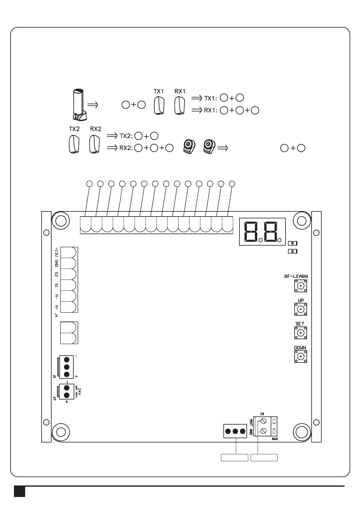
3.1. Wire Connection
3. Setup and Function Setting:
If the LED display is in normal performing refer to “4.2.1”, you can control the gate by either transmitters or the button
on the board: “UP”-clockwise moving, “SET”- stop and “DOWN”- Counterclockwise moving.
6
6 7 9
9
6 8 9
6 9
10 11
PPB-1
PPB-1, PKS-1:
PKS-1
SW1
SW3
SW4
SW5
3 4
PF-1
PF-1
AC INPUT
12345678910
1
23456
AC INPUT
1234567891011
1
23456
6
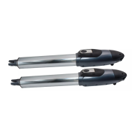
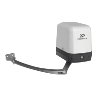
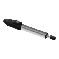
INSTRUCTIONS PL300E/PL400E/PL500E/PL800E SLIDING GATE OPENER USER MANUAL
LED2
LED1
AC INPUT
1234567891011121314
1
23456
1 2 3 4 5 6 7 8 9 10 11 12 13 14
Close
Stop
GND
Pb
Ph+
Ph2
Ph1
GND
EXT-
EXT+
GND
+13.75
Light
Open
AC INPUT
1234567891011
1
23456
Green Box Antenna
 Loading...