5. Additional Information:
12
INSTRUCTIONS PL500 SLIDING GATE OPENER USER MANUAL
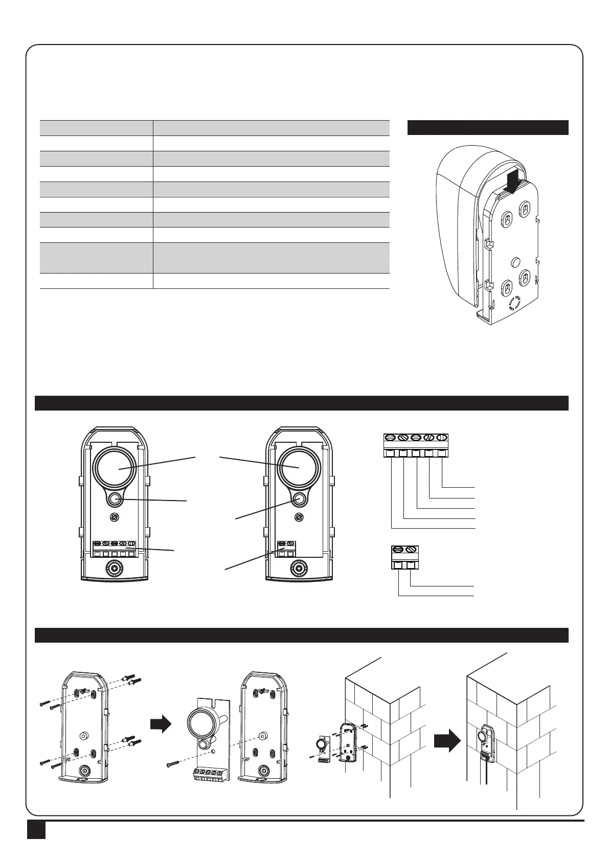
5.1. PHOTOCELL INSTALLATION GUIDE
The safety photocells are security devices for control automatic gates. Consist of one transmitter and one receiver
based in waterproof covers; it is triggered while breaking the path of the beams.
INSTALLATION:
Wire Connection of PH-2 Photocells See figure 4(2)
TX: Connect terminals 1 and 2 on the transmitter with the terminals Ph+ and GND on the P600B PCB.
RX: Connect terminals 1, 2 and 4 on the receiver with the terminals Ph+, GND and Ph1 on the P600B PCB.
And use an extra wire to connect terminals 2 and 5 on the receiver as a bridge.
Detection Method
Sensing Range
Input Voltage
Response Time
Emitting Element
Operation Indicator
Dimensions
Output Method
Current Consumption Max
Water Proof
Through Beam
25M
AC/DC 12~24V
100MS
IR LED
Red LED(RX): ON(When Beam is Broken), Green(TX):ON
96*45*43mm
Relay Output
TX: 35MA/Rx: 38MA (When beam aligned properly);
TX: 35MA/ Rx: 20MA (When beam is broken)
IP54
RX
RX
Lens
Beam Alignmnet
Indicator
Power Led
Indicator
Terminal Block
Power
Terminal Block
COM
N.C.
N.O.
GND
DC (12~24V)
GND
DC (12~24V)
TX
TX
SPECIFICATION:
Figure 4(3)
Figure 4(2)
Figure 4(1)
1 2 3 4 5
1 2 3 4 5 1 2
1 2
 Loading...