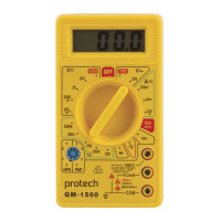
AC/DC VOLTAGE MEASUREMENT
1) Insert the black test lead banana plug into the negative COM jack.
2) Insert the red test lead banana plug into the positive VΩ jack.
3) Set the function switch to the VAC or VDC position. If the voltage to be measured is not known
beforehand, then set the switch to the highest range and reduce it until a satisfactory reading is
obtained.
4) Connect the test leads to the device of circuit being measured, then turn the device or circuit on.
5) Read the voltage on the display.
DC CURRENT MEASUREMENT
1) Insert the black test lead banana plug into the negative COM jack
2) For current measurements up to:
a. 200mA DC – Insert the red test lead banana plug into the VΩ jack.
b. 10A DC – insert the red test lead banana plug into the 10A jack.
3) Set the function switch to the desired position.
4) Remove power from the circuit under test, then open up the circuit at the point where you wish
to measure current.
5) Touch the black test probe tip to the negative side of the circuit.
6) Touch the red test probe tip to the positive side of the circuit.
7) Apply power to the circuit.
8) Read the current displayed on the display.
RESISTANCE MEASUREMENT
1) Insert the black test lead banana plug into the negative COM jack.
2) Insert the red test lead banana plug into the positive VΩ jack.
3) Set the function switch to the desired Ω position.
4) If the resistance being measured is connected to a circuit, then turn power off and discharge all
capacitors prior to measurement. Then connect he test leads to the circuit.
5) Read the resistance on the display.
DIODE TEST
1) Insert the black test lead banana plug into the negative COM jack.
2) Insert the red test lead banana plug into the positive VΩ jack.
3) Set the function switch to the position.
4) Touch the red test probe to the anode of the diode to be measured, and the black test lead to the
cathode.
5) Reverse the probe polarity by switching the probe position. Note this reading.
6) The diode or junction can be evaluated as follows:
a. If one reading shows a value and the other reading shows OL, the diode is good.
b. If both readings show OL, the device is open.
c. If both readings are very small or zero, the device or circuit is shorted.
TRANSISTOR MEASUREMENT
1) Set the function switch to the hFE position.
2) Determine whether the transistor is NPN or PNP.
3) Insert the Emitter, Base & Collector leads into the corresponding E, B & C holes in the hFE socket.
4) The meter will display the approximate hFE value at the base current of 10μA & VCD 2.8V.
MEASUREMENT SPECIFICATIONS
DC Voltage
(±1.0% of reading + 10 digits)
Overload protection: 220VAC for 200mV range, 1000VDC or 750VAC for other ranges.
5

 Loading...