1-Phase Power Supply Instruction Manual
Bedienungsanleitung für 1-Phasen Stromversorgungen
Hiccup
PLUS
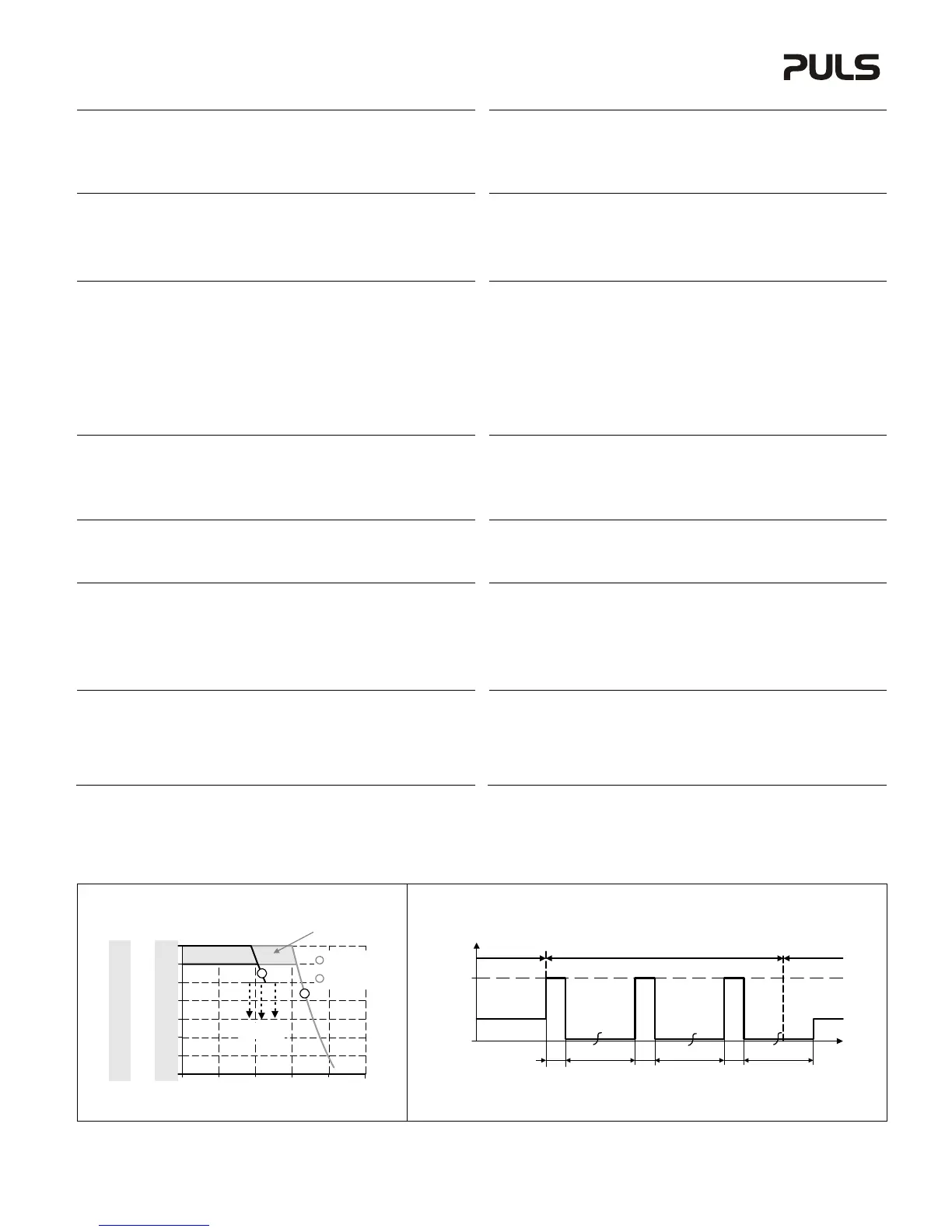
Overload Characteristic (see Fig. 1 and 2)
The output current is electronically controlled. During an overcurrent situation, the output voltage
will be reduced after a defined time. If the voltage falls below 20V for the 24V units, 30V for the
36V unit and 40V for the 48V units, the unit switches to the Hiccup
PLUS
mode. In this mode, the
output switches off followed by a restart attempt after 17s for 2s. This cycle is repeated as long as
the overload or short circuit exists. If the overload or short circuit has been cleared, the device will
operate normally.
Hiccup
PLUS
Überlastverhalten (siehe Bilder 1 und 2)
Der Ausgangsstrom ist elektronisch überwacht. Während einer Überstromsituation wird nach einer
bestimmten Zeit die Ausgangsspannung reduziert. Fällt die Spannung unter 20V bei 24V Geräten,
30V beim 36V Gerät oder 40V bei 48V Geräten schaltet das Gerät in den Hiccup
PLUS
Modus. In
diesen Modus schaltet das Gerät ab und macht nach 17s einen Startversuch mit einer Dauer von
2s. Der Vorgang wiederholt sich solange, bis die Überlast oder der Kurzschluss entfernt ist. Nach
entfernen der Überlast oder des Kurzschlusses schaltet das Gerät wieder in den Normalbetrieb.
DC-OK Relay Contact (see Fig. 3)
This feature monitors the output voltage, which is produced by the power supply, and is
independent of a return voltage from a unit which is connected in parallel.
Contact closes when the output voltage is above 90% of the adjusted value.
Contact opens when the output voltage is typ. below 90% of the adjusted value. Short dips will
be extended to a length of 250ms. Dips shorter than 1ms will be ignored.
Contact ratings: max.: 60Vdc 0.3A, 30Vdc 1A, 30Vac 0.5A, resistive load, min. current 1mA
DC-OK Relais Kontakt (siehe Bild 3)
Diese Funktion überwacht die vom Gerät erzeugte Ausgangsspannung und lässt sich von einer
rückwärts eingespeisten Spannung nicht beeinflussen (z.B.: bei Parallelschaltung)
Kontakt schließt, wenn die Ausgangsspannung typ. höher als 90% des eingestellten Wertes ist.
Kontakt öffnet, wenn die Ausgangsspannung typ. kleiner als 90% des eingestellten Wertes ist.
Kurze Einbrüche werden auf 250ms verlängert. Einbrüche kürzer 1ms werden ignoriert.
Kontakt Belastbarkeit: max.: 60Vdc 0.3A, 30Vdc 1A, 30Vac 0.5A, (R-Last), min. Strom 1mA
Isolation and Dielectric Strength (see Fig. 4)
The output voltage is floating and separated from the input according to SELV (IEC/EN 60950-1)
and PELV (EN 60204-1, EN 50178; IEC 62103, IEC 60364-4-41) requirements. Type and factory
tests are conducted by the manufacturer. Field tests may be conducted in the field using the
appropriate test equipment which applies the voltage with a slow ramp (2s up and 2s down).
Connect all phase-terminals together as well as all output poles before the test is conducted.
When testing, set the cut-off current settings to the value in the table below.
A B C D
Type Test (60s) 2500Vac 3000Vac 500Vac 500Vac
Factory Test (5s) 2500Vac 2500Vac 500Vac 500Vac
Field Test (5s) 2000Vac 2000Vac 500Vac 500Vac
Cut-off current setting >20mA >20mA >40mA >1mA
Galvanische Trennung und Isolationsfestigkeit (siehe Bild 4)
Die Ausgangsspannung hat keinen Bezug zur Erde oder Schutzleiter und ist zum Eingang nach
den SELV (IEC/EN 60950-1) und PELV (EN 60204-1, EN 50178, IEC 62103, IEC 60364-4-41)
Standards getrennt. Typ- und Stückprüfungen werden beim Hersteller durchgeführt. Wieder-
holungsprüfungen dürfen mittels geeigneten Prüfgenerators mit langsam (2s) ansteigenden und
abfallenden Spannungsrampen in der Anwendung erfolgen. Vor den Tests sind alle Phasen wie
auch alle Ausgangspole miteinander zu verbinden. Während der Tests darf die Strom-
bschaltschwelle nicht kleiner als der in der Liste angegebene Wert sein.
A B C D
Typprüfung (60s) 2500Vac 3000Vac 500Vac 500Vac
Stückprüfung (5s) 2500Vac 2500Vac 500Vac 500Vac
Wiederholungsprüfung (5s) 2000Vac 2000Vac 500Vac 500Vac
Strom- Abschaltschwelle >20mA >20mA >40mA >1mA
Remote Control of Output Voltage (see Fig. 6)
The shut-down input can also be used to remotely adjust the output voltage. A control voltage
applied on the shut-down input reduces the adjusted output voltage
Instructions:
1. Set the unit into “Single Use” mode
2. Set the output voltage adjustment to the maximum desired voltage.
3. Apply a control voltage to reduce the output voltage
Externe Steuerung der Ausgangsspannung (siehe Bild 6)
Mithilfe einer externen Steuerspannung am Shut-down Eingang kann die eingestellte
usgangsspannung in gewissen Grenzen reduziert werden.
nleitung:
1. Gerät in „Single Use“ Modus stellen
2. Ausgangsspannung mittels Potentiometer auf den maximal gewünschten Wert einstellen
3. Steuerspannung am Shut-down Eingang anlegen um die Ausgangsspannung zu reduzieren
Shut-down Input (see Fig. 7)
This feature allows a switch-off of the power supply with a control switch or an external voltage.
The shut-down function has no safety feature included. The shut-down occurs immediately while
the turn-on is delayed by 350ms. In a shut-down condition, the output voltage is <2V and the
output power is <0.5W.
„Shut-down“ Eingang (siehe Bild 7)
bschaltung des Gerätes durch einen Signalschalter oder eine Fremdspannung. Die Abschaltung
beinhaltet keine Sicherheitsfunktionen. Die Abschaltung erfolgt unverzögert, das
Wiedereinschalten mit einer Verzögerung von ca. 350ms. Im abgeschaltetem Zustand ist die
usgangsspannung <2V und die Ausgangsleistung <0,5W.
Single Use / Parallel Use Selector
This selector on the front of the unit enables a load sharing when power supplies are connected in
parallel. The “Parallel Use” mode regulates the output voltage in such a manner that the voltage at
no load is approx. 4% higher than at nominal load.
If no jumper is plugged in, the unit is also in “Single Use”. Factory setting is “Single Use”.
Instructions for parallel use:
The output voltage shall be adjusted to the same value (±100mV) in “Single Use” at the same load
condition on all units, or shall be left with the factory settings. Afterwards, the jumper on the front
of the unit shall be moved from “Single Use” to “Parallel Use”
„Single Use“ / „Parallel Use“ Steckbrücke
Diese Steckbrücke an der Frontseite des Geräts ermöglicht eine Lastaufteilung, wenn mehrere
Geräte parallel geschaltet sind. In „Parallel Use“ Modus ist die Ausgangsspannung so geregelt,
dass diese im Leerlauf um etwa 4% höher ist als bei Nennlast.
Ein nicht eingesteckter Jumper bedeutet auch „Single Use“. Werkseinstellung ist „Single Use“.
Anleitung für Parallelbetrieb:
Die Ausgangsspannung aller Geräte bei gleicher Belastung in „Single Use“ auf ±100mV genau
einstellen oder in Werkseinstellung belassen. Danach die Steckbrücke an der Front des Gerätes
von „Single Use“ auf „Parallel Use“ umstecken.
Indicators, LEDs
Overload LED DC-OK LED DC-OK Contact
Normal mode OFF ON Closed
During BonusPower
®
OFF ON Closed
Overload (Hiccup mode) flashing OFF Open
Output short circuit flashing OFF Open
Temperature Shut-down flashing OFF Open
ctive Shut-down input flashing OFF Open
Anzeigelampen
Overload LED DC-OK LED DC-OK Contact
Normalbetrieb AUS EIN geschlossen
Während BonusPower
®
AUS EIN geschlossen
Überlast (Hiccup- Modus) blinken AUS offen
usgangskurzschluss blinken AUS offen
Temperaturabschaltung blinken AUS offen
ktiver „shut-down“ Eingang blinken AUS offen
Fig. 1/ Bild 1
Output Characteristic /Ausgangskennlinie, typ.
Fig. 2/ Bild 2
Hiccup
PLUS
Overload and Short-Circuit Behavior / Hiccup
PLUS
Überlast- und Kurzschlussverhalten, typ.
Output Current
0V
0 50% 100%
4V
8V
12V
28V
16V
20V
24V
150% 200% 250%
24V
Unit
0V
6V
12V
18V
42V
24V
30V
36V
36V
Unit
0V
8V
16V
24V
56V
32V
40V
48V
48V
Unit
Hiccup
PLUS
mode
Adjustment range
A
B
A
B
Short-term (4s)
available
Continuously
available
Output Voltage
Output
Current
0
I
SC
17s 17s
17s
2s
2s
2s
t
Short -circuit
Normal
operation
Normal
operation
I
SC
:
24V units: 65A
36V unit: 50A
48V units: 35A
 Loading...