8
9
• External power supply (AC/DC) is to be connected to “Power” (9) jack
located on right side of the device.
• Please note that the central pin of the power supply that you
connect to the “power” jack of the riflescope, must have marking
“+”. The power supply may have marking .
• Connection of an external power supply (icon shows up on the data
panel) automatically cuts off power supply from batteries.
External power supply DOES NOT charge the rechargeable batteries
in the unit.
Attention! We suggest that you use battery packs EPS3 or EPS5
ensuring from 7 to 18 hours of operation.
Starting the unit and image setup
Install the batteries in accordance with the “Installation of batteries”
section or connect an external power supply.
Rotate the lens cap (1) 45 degrees counterclockwise to open and
remove it.
Turn on the “ON” button (7) the display will light up in a couple of
seconds.
If your sight has parallax adjustment option, set a distance
corresponding to 100 metres.
To adjust display brightness, rotate the encoder (5). Brightness level
from 0 to 20 is shown next to the icon on the data panel.
Press the encoder (5) to switch to display contrast setup mode (16).
The data panel shows icon and contrast level from 0 to 20 next to it.
Choose a still object that is, for instance, 100 metres away.
Rotate the lens focus knob (2) to acquire best possible image
sharpness.
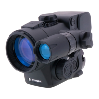
In low light conditions or in complete darkness attach and turn on the
built-in laser IR Illuminator by rotating the knob (6) clockwise (make
sure the IR is mounted).
Rotate the knob (6) to adjust IR power (icons on the data
panel): clockwise – to increase power; counterclockwise – to decrease
power. Icon means that the IR Illuminator was not installed.
When finished, turn off the attachment by pushing the “ON” button (7).
Close the lens cap (1).
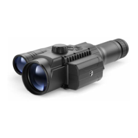
Choose an adapter with an insert of the required diameter (see table below for
reference) depending on the outer diameter of the bell of the daylight sight.
42 mm, 50 mm, 56 mm in adapter’s model name correspond to the optical
diameter of the sight’s bell. Adapter (18) with a set of inserts (21) are bought
separately.
Attention! An adapter must always be used together with an insert only.
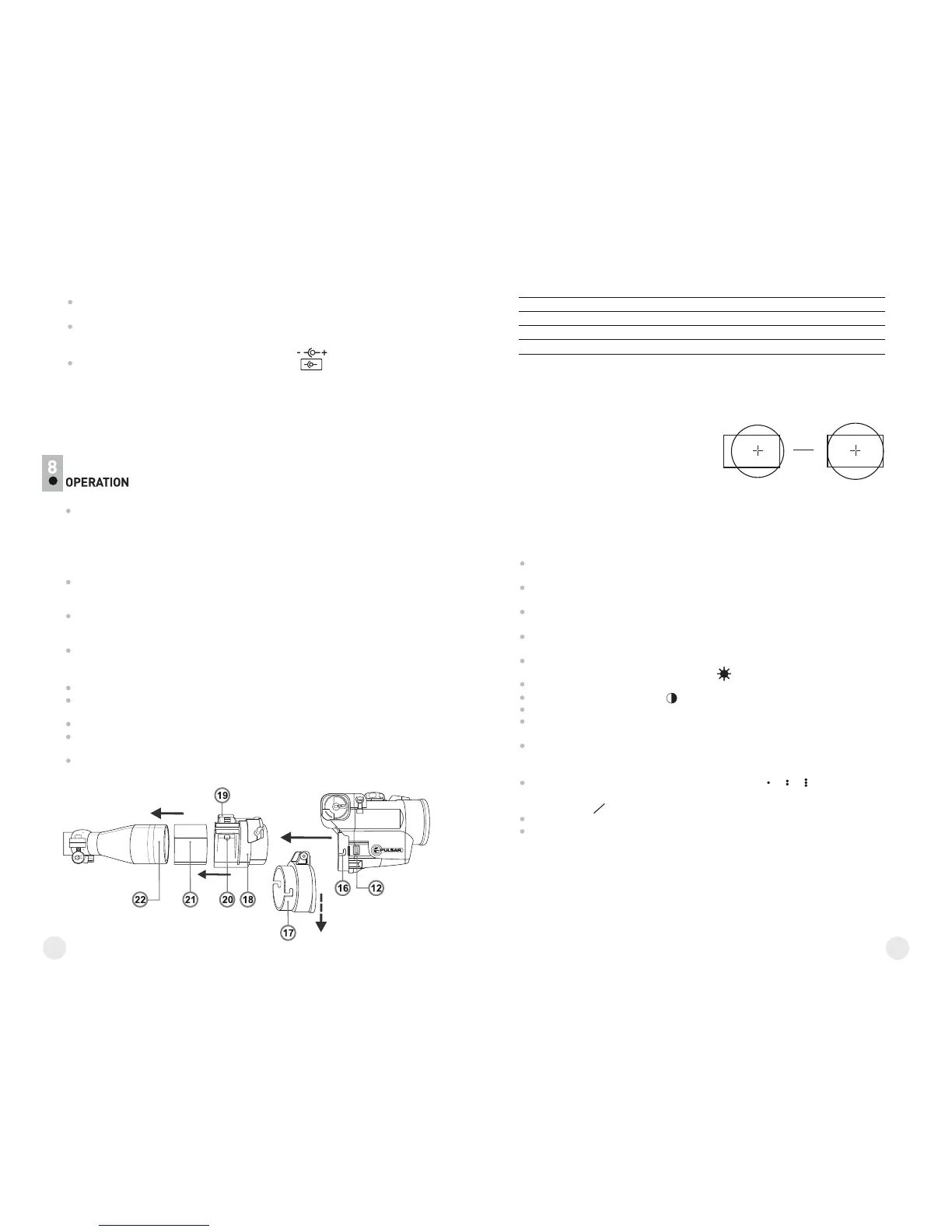
Unsnap the clamp (19) of the adapter (18) and mount the adapter on the
sight’s bell (22) so that its flat bottom part is parallel to the ground. Snap the
clamp.
If the clamp rotates freely, use a hex-nut wrench to tighten the screw (20) to
ensure that the adapter with the insert fit closely to the sight’s bell when the
clamp rotates.
Remove the cover (17) from the Cover Ring Adapter 42mm (#79121) by
turning it clockwise. To remove the cover from the Cover Ring Adapter
50 mm (#79122) or 56 mm (#79123), turn the cover counterclockwise.
See the marking on the adapters.
Insert the adapter into the attachment so that the teeth in the adapter’s
body enter the notches of the attachment (16).
Turn the attachment counterclockwise until it clicks.
To do the horizon adjustment, please refer to “Horizon adjustment
function” in section 10.
In order to remove the attachment, move the lock (12) to the right and
turn the attachment clockwise until it clicks. Pull the attachment and
remove it carefully.
Adapter name
Insert's inner diameter, mm
56 mm Cover Ring Adapter (#79123)
50 mm Cover Ring Adapter (#79122)
42 mm Cover Ring Adapter (#79121)
65 / 62 / 60
58.7 / 57 / 56
50 / 49 / 48 / 47
Attention! If you noticed that after mounting the attachment on your rifle, the image on
the display is off the centre of the field of view (pic. А), you can centre the image: unsnap
the clamp (19), incline the attachment to achieve image position as shown on image B.
Then snap the clamp and tighten the screw.
Important! Image position does not affect
shooting accuracy.
А B
IR IR
IR
IR
Mounting the attachment on daylight sight
 Loading...