11
For instance:
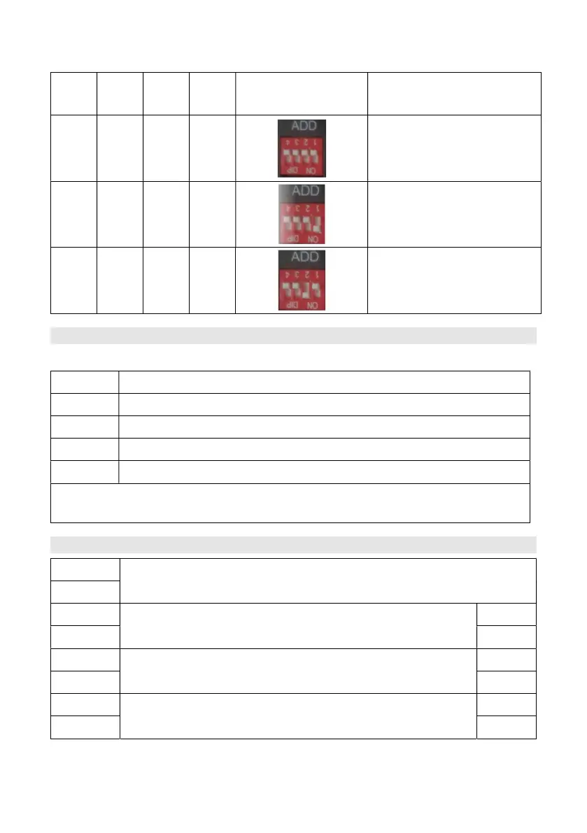
Dip1
Dip2
Dip3
Dip4
corresponding
Status
0 0 0 0
RS485:115200
CAN terminal resistance:
connected
1 0 0 0
RS485:9600
CAN terminal resistance:
connected
0 1 0 0
RS485: 115200
CAN terminal resistance:
disconnected.
For manufacturer or professional engineer to debug or service.
Pin3 232-TX
Pin4* +5~+12V for wake up
Pin5* GND for wake up
Pin6 232-RX
Pin8 232-GND
*Wake up signal shall ≥0.5Sec, current between 5~15mA. After send wake up signal, the
voltage shall disappear for normal operation.
Pin1
Input, passive signal. On: turn off battery. Off: normal.
Pin2
Pin3
Output1. On: stop charge.
+
Pin4 -
Pin5
Output2. On: stop discharge.
+
Pin6 -
Pin7
Output3. On: BMS error.
+
Pin8 -
Input terminals: BMS provide 5Vdc internally. External contactor control ON/OFF.
Output terminals: BMS control ON/OFF. External source request signal voltage ≤25V, current <0.3A.
 Loading...