Conexionado de control
1. Use para el cableado del circuito de control cables aislados, NEC
Clase 1, 600 volts como mínimo.
2. Si se va a hacer más de una conexión bajo el tornillo de un terminal
de la bornera de control, use un terminal tipo horquilla engarzado a
presión en los extremos de cable.
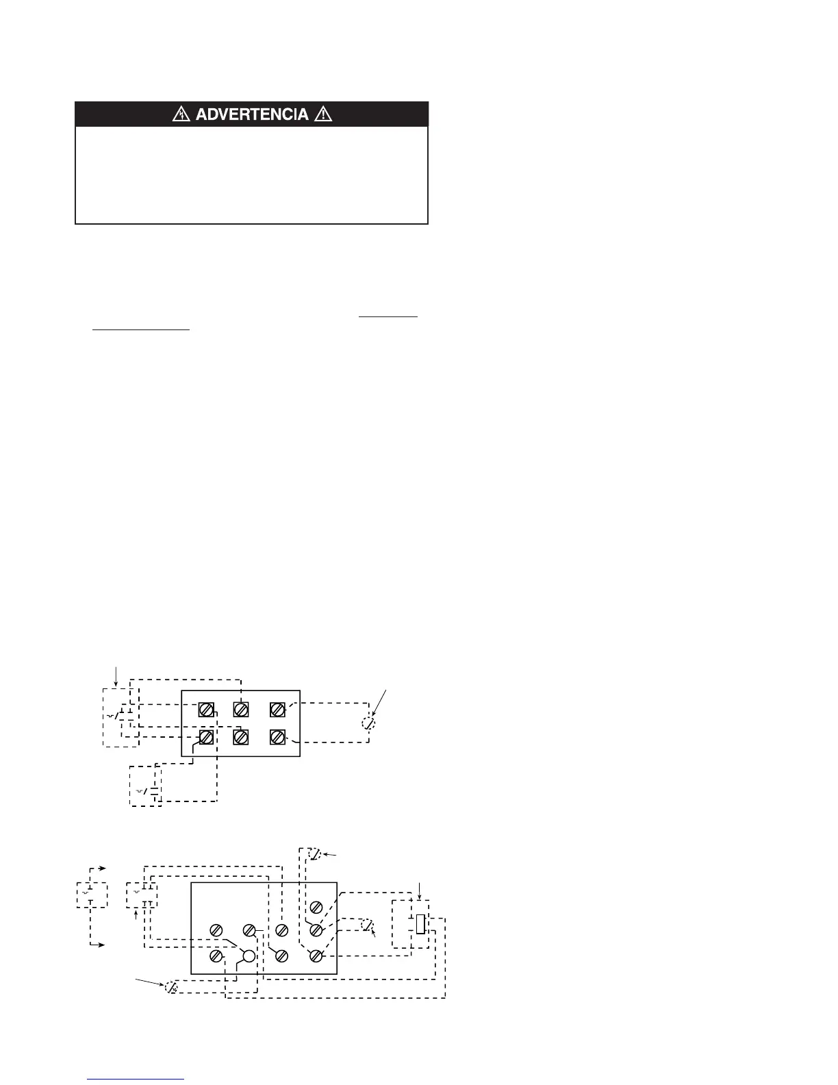
3. Para ver el diagrama de conexionado de las unidades no provistas
de contactor interno (3 y 5 kW), consulte la Figura 4.
NOTA: el cableado del termostato y del circuito de control deben ser
aptos para manejar la carga plena del calefactor (por ejemplo, el con-
sumo nominal del MUH0581 es 24 A).
4. Para ver el diagrama de conexionado de las unidades provistas de
contactor interno (unidades de 7 kW y mayores), consulte la Figura
5. El cableado de control debe tener un calibre 18 AWG como míni-
mo.
INSTRUCCIONES DE
OPERACIÓN
1. El calefactor debe instalarse correctamente antes de ponerlo en
funcionamiento.
2. Conecte la alimentación eléctrica al calefactor en el tablero de
distribución principal.
3. Donde sea aplicable, para ver la operación correcta de los controles
y accesorios que pueda utilizar el calefactor consulte las
instrucciones de los accesorios de control.
EN ALGUNOS TERMINALES DE LA BORNERA DE CON-
TROL ESTÁ PRESENTE LA TENSIÓN DE LÍNEA.
DESCONECTE SIEMPRE LA ALIMENTACIÓN ELÉCTRICA
DEL CALEFACTOR ANTES DE HACER CONEXIONES A LA
PLACA DE CONTROL, A FIN DE EVITAR UN RIESGO DE
CHOQUE ELÉCTRICO.
15
MT-1
MT-2
ROJO
ROJO
NEGRO
NEGRO
P2
H2
F 1
F 2
S
P1
H1
TERMOSTATO
INTERNO DE
2 ETAPAS
INTERRUPTOR DE VENTILADOR
REMOTO PARA VERANO (MRFS-1)
INTERRUPTOR DE VENTILADOR
PARA VERANO
NOTAS:
1. LA BORNERA DE CONTROL DE ESTE TIPO SE USA CON LOS MODE-
LOS MUH0321, MUH0371, MUH0381, MUH0521, MUH0571 Y MUH0581.
2. CUANDO LA UNIDAD SE CABLEA PARA CONEXIÓN MONOFÁSICA,
PUENTEE H1 CON H2. SI SE USA UN TERMOSTATO UNIPOLAR CON
LA UNIDAD MONOFÁSICA, CONECTE LOS CABLES DE CONEXIÓN
DEL TERMOSTATO A P1 Y H1.
3. LOS TERMOSTATOS PARA TENSIÓN DE LÍNEA EXTERNA DEBEN CON-
SIDERARSE COMO DE UNA ETAPA ÚNICAMENTE.
T
T
MT-1
MT-2
NEGRO, a W1
ROJO, a R
TERMOSTATO
INTERNO DE
2 ETAPAS
TERMOSTATO DE
RECUPERACIÓN
DE CALOR MHRT O
INTERRUPTOR DE
VENTILADOR REMOTO
(MRFS-2)
NEGRO
ROJO
ROJO
NEGRO
C
RW1
W2
F 2
F 1
G
T R
T
S
S
INTERRUPTOR DE VENTILADOR
REMOTO PARA VERANO (MRFS-1)
RELÉ DE VENTILADOR
(PARA MRFS-2 Y MHRT)
INTERRUPTOR
DE VENTILADOR
PARA VERANO
Figura 5. Bornera de control (para calefactores con contactor)
NOTAS:
1. LA BORNERA DE CONTROL DE ESTE TIPO NO SE USA CON LOS
MODELOS MUH0321, MUH0371, MUH0381, MUH0521, MUH0571 NI
MUH0581.
2. CUANDO USE UN TERMOSTATO DE 2 ETAPAS, QUITE EL PUENTE
QUE UNE W1 Y W2.
3. *SÓLO UNO DE ESTOS ACCESORIOS PUEDE INSTALARSE EN UN
CALEFACTOR ÚNICO.
4. LOS TERMOSTATOS PARA TENSIÓN DE LÍNEA EXTERNA DEBEN
CONSIDERARSE COMO DE UNA ETAPA ÚNICAMENTE.
Figura 4. Bornera de control (para calefactores sin contactor)
 Loading...