GNSS Module Series
LC76G_Series_EVB_User_Guide 13 / 33
3.2. EVB Interfaces
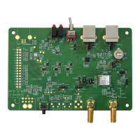
The EVB interfaces are detailed in the table below.
Table 3: Detailed EVB Interfaces
Function Interfaces Description
Power Supply
J509
USB to UART
Power supply input:
DC power supply: 4.5–5.5 V, Typ. 5.0 V
Current capability should be > 100 mA
Communication
Interface
J509
USB to UART
Supports RTCM and standard NMEA
message, PAIR/PQTM message and binary
data, and firmware upgrade.
SMA Connectors
J103
Used for connecting GNSS antenna.
1PPS connector
Used for testing 1PPS signal.
Signal Indication
D514
Indication LEDs
(Red)
Bright: EVB is powered well.
Extinct: EVB is not powered.
VCC
(Green)
Bright: Module is powered well.
Extinct: Module is not powered.
D520
Indication LEDs
1PPS
(Red)
Flashing: Successful position fix.
Frequency: 1 Hz.
Extinct: No position fix.
(Green)
Unsupported.
Switches and Buttons
S201
Module power switch
Powers the module VCC on/off.
S503
Short press the button to reset the module.
The J402 test point of LC76G EVB is shown below:

 Loading...