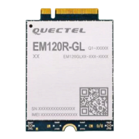
LTE-A Module Series
EM120R-GL&EM160R-GL Hardware Design
EM120R-GL&EM160R-GL_Hardware_Design 3 / 79
Contents
About the Document ................................................................................................................................... 2
Contents ....................................................................................................................................................... 3
Table Index ................................................................................................................................................... 5
Figure Index ................................................................................................................................................. 7
1 Introduction .......................................................................................................................................... 9
1.1. Safety Information ..................................................................................................................... 10
2 Product Concept ................................................................................................................................ 11
2.1. General Description .................................................................................................................. 11
2.2. Key Features ............................................................................................................................. 12
2.3. Functional Diagram ................................................................................................................... 14
2.4. Evaluation Board ....................................................................................................................... 15
3 Application Interfaces........................................................................................................................ 16
3.1. Pin Assignment ......................................................................................................................... 17
3.2. Pin Description .......................................................................................................................... 18
3.3. Power Supply ............................................................................................................................ 23
3.3.1. Decrease Voltage Drop .................................................................................................. 23
3.3.2. Reference Design for Power Supply.............................................................................. 24
3.4. Turn-on and Turn-off Scenarios ................................................................................................ 25
3.4.1. Turn on the Module ........................................................................................................ 25
3.4.1.1. Turn on the Module with a Host GPIO ................................................................ 25
3.4.1.2. Turn on the Module Automatically ....................................................................... 26
3.4.1.3. Turn on the Module with Compatible Design ...................................................... 26
3.4.2. Turn off the Module ........................................................................................................ 28
3.4.2.1. Turn off the Module through FULL_CARD_POWER_OFF#............................... 28
3.4.2.2. Turn off the Module through AT Command ......................................................... 28
3.5. Reset ......................................................................................................................................... 30
3.6. (U)SIM Interfaces ...................................................................................................................... 32
3.7. USB Interface ............................................................................................................................ 37
3.8. PCIe Interface ........................................................................................................................... 39
3.8.1. Endpoint Mode ............................................................................................................... 40
3.8.2. USB Version and PCIe Only Version ............................................................................. 42
3.9. PCM Interface* .......................................................................................................................... 43
3.10. Control and Indicator Signals* .................................................................................................. 45
3.10.1. W_DISABLE1# Signal.................................................................................................... 45
3.10.2. W_DISABLE2# Signal.................................................................................................... 46
3.10.3. WWAN_LED# Signal...................................................................................................... 47
3.10.4. WAKE_ON_WAN# Signal .............................................................................................. 48
3.10.5. DPR ................................................................................................................................ 49
3.10.6. ANT_CONFIG Signal ..................................................................................................... 50
3.11. COEX UART Interface* ............................................................................................................. 50

 Loading...