EasyManuals Logo
Home>Quectel>Control Unit>LTE-A Module Series

Quectel LTE-A Module Series User Manual

Quectel LTE-A Module Series
86 pages
To Next Page IconTo Next Page
To Previous Page IconTo Previous Page
Page #45 background imageLoading...
Page #45 background image
LTE-A Module Series
EM120R-GL&EM160R-GL Hardware Design
EM120R-GL&EM160R-GL_Hardware_Design 44 / 79
PCM_CLK
PCM_SYNC
PCM_OUT
MSB
LSB
PCM_IN
125 μs
MSB
1 2 3231
LSB
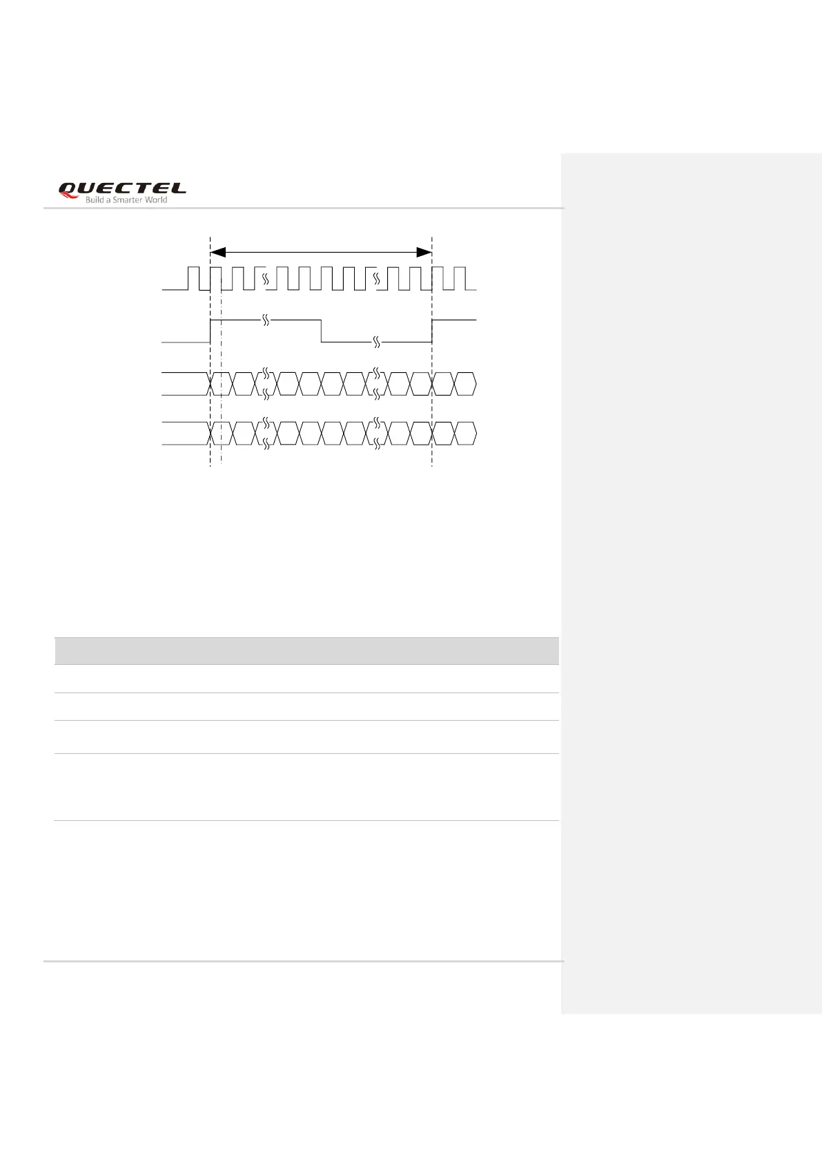
Figure 26: Auxiliary Mode Timing
The following table shows the pin definition of PCM interface which can be applied on audio codec
design.
Table 14: Pin Definition of PCM Interface
The clock and mode can be configured by AT command, and the default configuration is master mode
using short frame synchronization format with 2048 kHz PCM_CLK and 8 kHz PCM_SYNC. Refer to
document [3] for details about AT+QDAI command.
Pin Name
Pin No.
I/O
Description
Comment
PCM_DIN
22
DI
PCM data input
1.8 V power domain
PCM_DOUT
24
DO
PCM data output
1.8 V power domain
PCM_SYNC
28
IO
PCM data frame
synchronization
1.8 V power domain
PCM_CLK
20
IO
PCM data bit clock
In master mode, it is an
output signal.
In slave mode, it is an input
signal.
1.8 V power domain.
If unused, keep it open.

Table of Contents

Questions and Answers:

Question and Answer IconNeed help?

Do you have a question about the Quectel LTE-A Module Series and is the answer not in the manual?

Quectel LTE-A Module Series Specifications

General IconGeneral
BrandQuectel
ModelLTE-A Module Series
CategoryControl Unit
LanguageEnglish

Related product manuals