M20 EVB User Guide
3.2. Audio interface
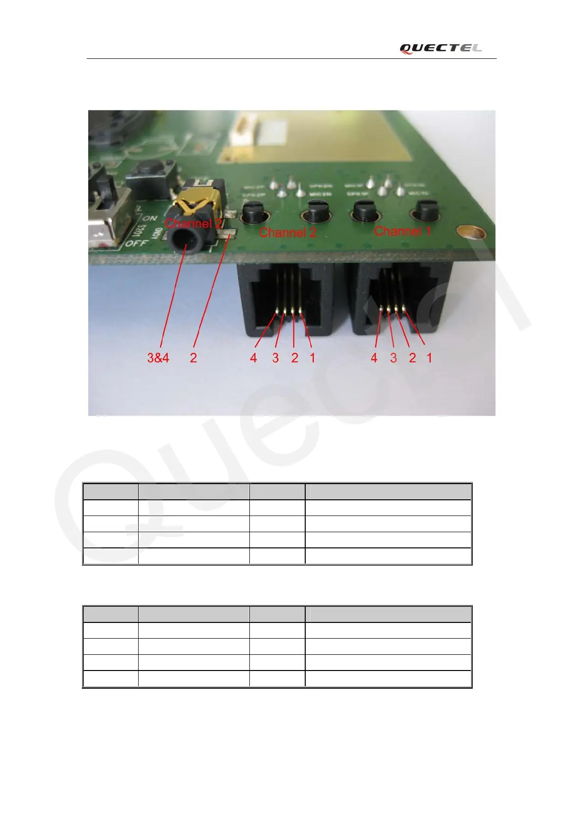
Figure 5: Audio interface
Table 3: Pins of audio channel 1
Pin Signal I/O Description
1 MIC1N I Negative microphone input
2 SPK1N O Negative receiver output
3 SPK1P O Positive receiver output
4 MIC1P I Positive microphone input
Table 4: Pins of audio channel 2
Pin Signal I/O Description
1 MIC2N I Negative microphone input
2 AGND AGND of audio circuits
3 SPK2P O Positive receiver output
4 MIC2P I Positive microphone input
A headset or handset can be used in audio channel 2.
M20_EVB_UGD_V1.01 - 12 -

 Loading...