12
TECHNICAL DATA
GB
AFR 700/1000/1400W - REV012A
Quick
®
reserves the right to introduce changes to the equipment and the contents of this manual without prior notice.
In case of discordance or errors in translation between the translated version and the original text in the Italian language, reference will be made to the Italian or English text.
F
C
E
H
I
A
B
D
F
A
C
D
E
F
G
H
B
I
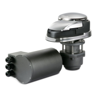
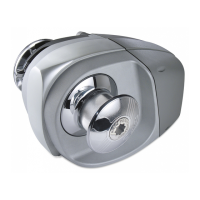
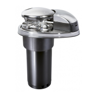
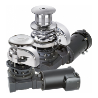
700 / 1000 / 1400 W ARIES - FLAIR - / D 700 / 1000 / 1400 W RIDER - / D
• ((5)
On request, shafts and studs can be supplied for greater deck thicknesses.
1° EXAMPLE: FLAIR724D
FLAIR 7 24 D
a
RIDER 10 12 -
Name of the line:
[ ARIES ] =
oval base in aluminium
[ FLAIR B ] =
oval base in black fiber-glass
[ FLAIR W ] =
oval base in white fiber-glass
[ RIDER ] =
round
base in aluminium
Motor output:
[ 7 ] =
700 W
[ 10 ] =
1000 W
[ 14 ] =
1400 W
Motor supply voltage:
[ 12 ] =
12 V
[ 24 ] =
24 V
Drum:
[ D ] =
with drum
[ - ] =
without drum
HOW TO IDENTIFY THE WINDLASS THROUGH THE CODE:
a b c d
a b c d a b c d
2° EXAMPLE: RIDER1012
a
a
a
a
a
a
a
• (1) After an initial period of use. • (2) Measurements taken with a gypsy for a 8 mm chain.
• (3) Minimum allowable value for a total length L<20m (see pag. 44). Determine the cable size according to the length of the wiring.
• (4) With circuit breaker designed for direct currents (DC) and delayed-action (thermal-magnetic or hydraulic-magnetic).
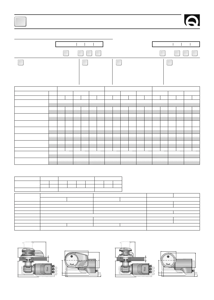
DIMENSIONS
mm (inch)
ARIES/FLAIR - / D RIDER - / D ARIES/FLAIR - / D RIDER - / D
700W 1000W 700W 1000W 1400W
A
98 (3” 27/32) 100 (3” 15/16) 98 (3” 27/32) 100 (3” 15/16)
B
161,4 (6” 23/64) 163,4 (6” 7/16) 161,4 (6” 23/64) 163,4 (6” 7/16)
C
141 (5” 9/16) 179 (7”) 179 (7”)
D
250 (9” 27/32) 159 (6” 1/4) 250 (9” 27/32) 159 (6” 1/4)
E
141 (5” 9/16) 167 (6” 37/34)
F
87 (3” 7/16) Ø 155 (6” 3/32) 87 (3” 7/16) Ø 155 (6” 3/32)
G
78 (3” 23/32) - 78 (3” 23/32) -
H
330 (13”) 340 (13” 3/8) 330 (13”) 340 (13” 3/8) 375 (14” 49/64)
I
25 ÷ 50 mm (31/32” ÷ 1” 31/32)
(5)
30 ÷ 50 mm (1”3/32 ÷ 1” 31/32)
(5)
MODELS ARIES – / D FLAIR – / D RIDER – / D
MOTOR POWER W 700 1000 1400 700 1000 1400 700 1000 1400
Motor supply voltage V 12 24 12 24 12 24 12 24 12 24 12 24 12 24 12 24 12 24
Maximum pull
kg 850 1000 1100 850 1000 1100 850 1000 1100
lb 1873,9 2204,6 2425,1 1873,9 2204,6 2425,1 1873,9 2204,6 2425,1
Maximum working load
kg 250 300 370 450 450 500 250 300 370 450 450 500 250 300 370 450 450 500
lb 551,1 661,4 815,7 992,1 992,1 1102,3 551,1 661,4 815,7 992,1 992,1 1102,3 551,1 661,4 815,7 992,1 992,1 1102,3
Working load
kg 80 100 120 150 150 170 80 100 120 150 150 170 80 100 120 150 150 170
lb 176,4 220,5 264,5 330,7 330,7 374,8 176,4 220,5 264,5 330,7 330,7 374,8 176,4 220,5 264,5 330,7 330,7 374,8
Current absorption
working load
(1)
A 90 55 140 80 155 85 90 55 140 80 155 85 90 55 140 80 155 85
Maximum chain speed
(2)
m/min 27,4 26,4 39,6 40,9 33,0 29,7 27,4 26,4 39,6 40,9 33,0 29,7 27,4 26,4 39,6 40,9 33,0 29,7
ft/min 89,9 86,6 129,9 134,2 108,3 97,4 89,9 86,6 129,9 134,2 108,3 97,4 89,9 86,6 129,9 134,2 108,3 97,4
Maximum chain speed @
working load
(2)
m/min 14,4 14,8 20,4 21,4 17,5 20,5 14,4 14,8 20,4 21,4 17,5 20,5 14,4 14,8 20,4 21,4 17,5 20,5
ft/min 47,2 48,6 66,9 70,2 57,4 67,3 47,2 48,6 66,9 70,2 57,4 67,3 47,2 48,6 66,9 70,2 57,4 67,3
Motor cable size
(3)
mm
2
25 10 35 16 50 25 25 10 35 16 50 25 25 10 35 16 50 25
AWG372503372503372503
Protection circuit breaker
(4)
A 50 40 80 50 100 50 50 40 80 50 100 50 50 40 80 50 100 50
Weight
modell without drum
kg 17,4 18,5 20,8 16,5 17,6 19,9 16,0 17,1 19,4
lb 38,4 40,8 45,8 36,4 38,8 43,9 35,3 37,7 42,8
Weight
modell with drum
kg 19,3 20,4 22,7 18,4 19,5 21,8 18,0 19,1 21,4
lb 42,5 45,0 50,0 40,6 43,0 48,1 39,7 42,1 47,2
(*) For the gypsy codes, please consult the exploded drawing on
page 16.
(**) ISO EN 818-3.
GYPSYES (*) 6 mm 8 mm - 5/16” 10 mm - 3/8”
Chain size
6 mm 6 mm 8 mm 8 mm 5/16” 5/16” 10 mm 10 mm 3/8”
DIN 766 ISO DIN 766 ISO G4 BBB DIN 766 ISO G4
Rope size (**) 1/2” 1/2” - 9/16” - 5/8” -
 Loading...