PROPELLER
CONTROL PANEL
To install the control panel, consult the “TCD 1022 - TCD 10422 - TCD 1044 instruction manuals.
LOCTITE
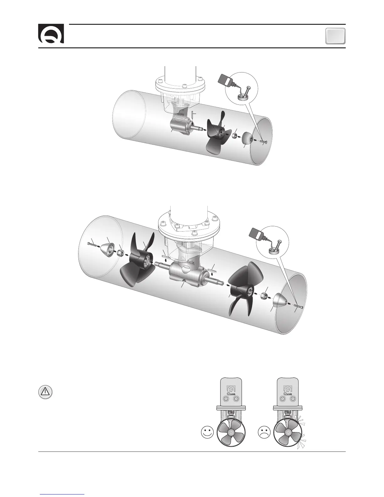
WARNING:
on conclusion of assembly, make sure that
the propeller is exactly positioned at the central point
of the tunnel.
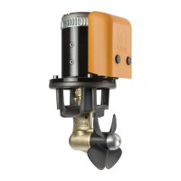
PROPELLER FITTING
Insert the drive pin
A
into the hole on the gearleg shaft
B
; assemble the propeller
C
to the gearleg, making it fit in correctly with
the drive pin
A
; fix the propeller with the self-braking nut
D
. The anode
E
must be locked with the screw
F
soaked with building
adhesive (such as Loctite).
A
B
C
D
E
F
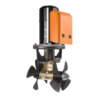
PROPELLERS FITTING
Insert the drive pins
A
into the hole on the gearleg shafts
B
; assemble the propellers
C
to the gearleg, making it fit in correctly
with the drive pins
A
; fix the propellers with the self-braking nuts
D
.
The anodes
E
must be locked with the screws
F
soaked with building adhesive (such as Loctite).
LOCTITE
A
B
C
E
G
F
A
D
E
F
G
 Loading...