QT/QTS Series Quincy Compressor
2022208700, September 2018 39
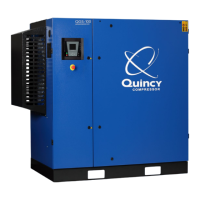
Step 3) Lay a straightedge across the top outer
surface of a drive belt from pulley to sheave.
Step 4) At the center of the span, perpendicu-
lar to the belt, apply pressure to the outer surface
of the belt with a belt tension gauge (refer to Fig.
5-2, Belt Tension Gauge). Force the belt to the
predetermined deflection (refer to Step 2 above).
Record the reading on the belt tension gauge and
compare to the chart following Fig 5-1. The de-
flection force reading should be within the minimum
and maximum values shown. Adjust belt(s) accord-
ingly. New belts should be initially tensioned to the
maximum value plus 33% (multiply by 1.33).
Step 5) Recheck the tension of the new belts
several times in the first 50 hours of operation
and adjust if necessary. Thereafter, check belt
tension on a regular basis (refer to SECTION 5,
Maintenance Schedule).
Pressure Switch Adjustment
Pressure switches provided by Quincy Compressor
are pre-set at the factory and usu ally do not require
adjustment. However, the following procedures can
be performed by a qualified electrician to adjust
the pressure switch.
Step 1) Remove the pressure switch cover.
Step 2) While the compressor is running, screw
the spring loaded adjustment screw in (clockwise)
to increase the amount of air pressure required to
open the switch and stop the unit. Screw the spring
loaded adjustment screw out (counterclockwise)
to decrease the amount of air pressure required
to open the switch and stop the unit.
Electric power always exists inside the pressure switch whenever
the compressor package is connected to a power supply. Be careful
not to touch any electrical leads when adjusting the pres sure
switch.
Never exceed the designed pressure for the system or overload the
motor beyond its Maximum Amp Draw.
* Full Load Amps x Service Factor = Maximum Amp Draw
Never assume a compressor is safe to work on just because it
is not operating. It may be in the automatic stand-by mode and
may restart any time. Follow all safety precautions outlined in
SECTION 5, Stopping For Maintenance.
WARNING !
WARNING !
WARNING !
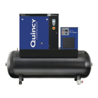
Fig. 5-3 Typical Pressure Switch
PRESSURE
ADJUSTMENT
SCREW
ELECTRICAL
CONTACTS
Fig. 5-2 Belt Tension Gauge
POCKET CLIP
SLIDING
RUBBER O-RINGS
DEFLECTION
FORCE SCALE
(READ DOWN)
DEFLECTION
DISTANCE
SCALE
(READ UP)
* Full load amps (FLA) & Service Factor can be found on the motor nameplate.
 Loading...