Do you have a question about the Raymarine Raytheon R20X and is the answer not in the manual?
| Power Output | 2 kW |
|---|---|
| Rotation Speed | 24 RPM |
| Frequency | 9.4 GHz (X-Band) |
| Power Supply | 12-24 V DC |
| Antenna Size/Length | 24 inches |
General radar specifications: range, discrimination, environmental conditions, and input power.
Procedures for installing the scanner unit, covering location selection and mounting.
Criteria for selecting an adequate mounting location for the scanner unit for optimal performance.
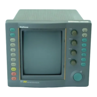
Procedures for installing the display unit, covering location selection and mounting.
Guidance on selecting an ideal location for the display unit for optimal viewing and minimal interference.
Procedure for connecting DC power, including wire size recommendations and polarity.
Instructions for properly grounding the radar system for effective RF ground.
Steps for initial operation, checkout, and post-installation adjustments.
Final inspection checks before powering up the radar system.
Steps for performing an operational checkout of the radar system after installation.
Necessary post-installation adjustments for optimal radar performance.
Overview of the radar system's operating controls and their functions.
Detailed explanation of the functions of various operating controls like Power, Range, VRM, EBL.
Adjusting receiver tuning for maximum target echoes and optimal indicator display.
Adjusting receiver sensitivity and target visibility for clear radar displays.
Setting up approach and exit alarm zones for target detection.
Optimizing radar tuning for maximum target echoes and clear display.
Adjusting receiver sensitivity and target visibility for optimal radar performance.
Using the radar for navigation, including position fixing and collision avoidance.
Methods for obtaining a radar position fix using navigational points and charts.
Using radar for collision avoidance, including constant bearing and course change actions.
Tips for user maintenance to ensure satisfactory operation and avoid premature equipment failure.
Procedures for making adjustments after component replacement or suspected faults.
Adjusting display unit parameters: intensity, focus, and sync.
Adjusting scanner unit parameters: AVR voltage, frequency, and tune indicator.
Procedures and guidelines for identifying and diagnosing radar system faults.
Procedures and guidelines for identifying and diagnosing radar system faults.
Troubleshooting steps for range rings visible but no noise or echoes.
Troubleshooting steps for noise/rings visible, but no echoes detected.
Troubleshooting steps for poor sensitivity and dim echo display.
Technical description of the transmitter, including modulator and magnetron.
Detailed technical description of the line-type pulser modulator, its components, and operation.
Technical details of the magnetron transmitter, its operating voltage, and current.
Technical description of the receiver unit, including MIC Frontend and Receiver PCB.
Technical description of the MIC Frontend, its amplifier, mixer, and local oscillator.
Technical description of the Receiver PCB, including IF amplifier, detector, video, tuning, Gain-STC, and MBS circuits.
Technical description of the power supply unit, including AVR and converter circuits.
Technical description of the Main Control PCB, including video input, A/D converter, clock generator, and buffer memory.