EasyManua.ls Logo

Raypak TempTracker mod+ Hybrid - User Manual

Raypak TempTracker mod+ Hybrid
56 pages
Print Icon
To Next Page IconTo Next Page
Loading...
HTC# 059105-00D
F
H
J
Power
CAUTION:
Risk of Electric Shock.
More than one disconnect switch may be required
to de-energize the equipment before servicing.
PWR
L N
1 2
E
3 4
F
5 6
G
7 8
H
9 10
I
11 12
EXTENSION
MODULE
RS-485
Ext A
INPUT RATINGS:
115VAC 60Hz, 12VA MAX
Use Copper Conductors Only.
OUTPUT RATINGS:
120VAC, 6A RESISTIVE
1A PILOT DUTY, 15A TOTAL
FOR ALL CIRCUITS
E
G
I
Comm
Ext B
K
M
O
L
N
P
1514
VLTmA
CUR / VLT
181716
VLTmAGND
CUR / VLT
212019
VLTmAGND
CUR / VLT
242322
VLTmAGND
CUR / VLT
J
11 12
K M OL N P
E F G H
K ML N
13
GND
16
GND
19
GND
22
GND
2726
VLTmA
CUR / VLT
302916
VLTmAGND
CUR / VLT
25
GND
28
GND
I J
O P
ENCLOSED
ENERGY
MANAGEMENT
EQUIPMENT
99RA
HYBRID







P/N 241382 REV.3
Cat.# 5000.69 04/15/11
SYSTEM
A
B
C
D
1
2
RUNPROGRAM
DO NOT APPLY ANY VOLTAGE
TO INPUT TERMINALS
3
4
5
6
7
8
9
10
11
12
13
15
14
17
16
18
20
19
21
24
23
29
25
27
26
28
32
30
31
L
N
-
+
+
T
T
O
O
RS-485
mA
GND
VLT
SYS
A
B
C
D
PWR
CUR / VLT
A
-
+
+
mA
GND
VLT
-
+
+
mA
GND
VLT
+
+
mA
22
-
GND
VLT
+
mA
TEMP
OUTDOOR
O
O
TEMP
SYSTEM
EXTENSION
MODULE
CUR / VLT
B
CUR / VLT
C
CUR / VLT
D
PROVE
/DHW
SHUTDOWN
/SETBACK
FOR ALL CIRCUITS
120VAC, 6A RESISTIVE
OUTPUT RATINGS:
1A PILOT DUTY, 15A TOTAL
115VAC 60Hz , 30VA MAX
INPUT RATINGS:
USE COPPER WIRE,
CLASS 1 WIRE ONLY.
CAUTION
: RISK OF ELECTRIC SHOCK
More than one disconnect switch may be required
to de-energize the equipment before servicing.
ENCLOSED
ENERGY
MANAGEMENT
EQUIPMENT
99RA
/TSTAT
HYBRID



Table of Contents

Question and Answer IconNeed help?

Do you have a question about the Raypak TempTracker mod+ Hybrid and is the answer not in the manual?

Raypak TempTracker mod+ Hybrid Specifications

TempTracker mod+ Hybrid

Operating Environment IconOperating Environment
operating temperature20°F/-6°C to 130°F/54°C
operating humidity20% to 80% non-condensing
control sensor rangesminus 35°F/-37°C to 250°F/121°C
Power IconPower
voltage input120 VAC 60 Hz
power consumption12 VA Max
output relay ratings1 Amp inductive (⅛ HP), 6 Amp resistive at 120 VAC 60 Hz, 15 A total for all circuits
Weight and Dimensions IconWeight and Dimensions
dimensions11"W x 9" H x 3 ¾" D
weight2.5 pounds

TempTracker mod+ Hybrid

Power IconPower
output relay ratings1 Amp inductive (⅛ HP), 6 Amp resistive at 120 VAC 60 Hz, 15 A total for all circuits
power backupLithium coin battery, 100 days minimum
add-on extension panelsup two Extension Panels using RS485 (RJ45 or RJ11)
Temperature Control IconTemperature Control
ignition point1 to 50%
modulation start point0 to 100%
outdoor cutoff range20°F/-6°C to 100°F
Operating Environment IconOperating Environment
minimum water temperature50°F/10°C to 170°F/77°C
maximum water temperature90°F/32°C to 240°F/116°C
offset adjustmentminus -40°F°/-22°C° to plus 40°F°/22°C°

Extension

Output Specifications IconOutput Specifications
boiler outputs(6) N.O. S.P.S.T.
modulating output types(6) 4-20mA and 0-10V
output relay ratings1 Amp inductive (⅛ HP), 6Amp resistive at 120 VAC 60 Hz, 15 A total for all circuits

Summary

Hybrid Logic Overview

Outdoor Reset Concept

Installation

Mounting the Enclosure

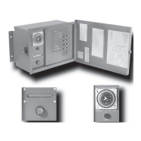
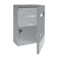
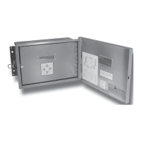
Provides instructions on selecting a location and mounting the control enclosure.

Install the Sensors

System Sensor Installation

Details the installation procedure for the system temperature sensor.

Outdoor Sensor Installation

Explains the proper placement and mounting of the outdoor air sensor.

Wiring

Wiring the Power

Instructions for connecting the 120VAC power supply to the control.

Wiring the Sensors

Guidance on connecting system and outdoor sensors, including shield wiring.

Wiring the Shutdown, Tstat, or Setback

Describes wiring for shutdown, thermostat, or setback inputs.

Wiring the System Components

Wiring the Prove

Details how to wire the Prove input for system component verification.

Wiring the Boilers

Wiring Boiler Activation or On;Off Staging Boilers

How to wire N.O. relay contacts for boiler activation or staging.

Wiring Multi-Stage Boilers

Details wiring for multi-stage boilers using 0-10V output signals.

Wiring to Modulating Boilers

Explains how to connect boilers for modulating control.

Wiring the 4-20 mA Modulating Boilers

Wiring the Voltage Modulating or Staging Boilers

Covers connecting voltage modulating or staging boilers.

Connecting to the Extensions and 4-20 mA EMS Interface

Connecting to BACnet Interface Module

Hybrid Startup Menu

Modulating and Staging Startup Menu

Startup Settings

Startup Sequence

Outlines the initial self-diagnostic test and system parameter setup.

Boiler Type

Configures boiler types as Modulation, Staging, or Hybrid.

Sensor Type

Selects sensor type for temperature display and reset ratio calculations.

EMS 4 mA and 20 mA Set Points

Switch Set Point

Defines the target temperature for switching between boiler groups.

Switch Delay

Hybrid Modulating Boiler Settings

Hybrid Staging Boiler Settings

Staging Mode

Modulating Output Type

Configures the signal type (4-20mA, 0-10V) for modulating boilers.

Staging Boiler Settings

Startup Settings (Continued)

Prove;Indirect Domestic Hot Water (DHW) Priority

Configures input terminals for Prove, DHW Priority, or No Priority.

Indirect Domestic Hot Water Set Point

Shutdown;Tstat;Setback Mode

Determines functionality of terminals for shutdown, thermostat, or setback.

BACnet MS;TP Startup Menu

BACnet Mode

Enables or disables BACnet MS/TP communication capability.

BACnet Baud Rate

Sets the communication baud rate for the BACnet MS/TP network.

Hybrid Operating Menu

Modulating and Staging Operating Menu

Setting the Control to Factory Defaults

Operating Settings

Outdoor Cutoff Temperature

System Settings

Modulating Boiler Operating Settings

Staging Boiler Operating Settings

Day;Night Schedule

Boiler Stage Menu

Display Messages

Boiler Stage Settings

Allows adjustment of individual boiler operations and settings.

Mode

Troubleshooting

Display shows Sensor OPEN or SHORT

Guides on diagnosing sensor wiring issues causing OPEN or SHORT readings.

Display shows an Incorrect Temperature

Provides steps to troubleshoot incorrect temperature readings from sensors.

No Heat

Lists potential causes and solutions for lack of heating operation.

Too Much Heat

Offers solutions for excessive heating conditions.

Too Little Heat

Boilers are Short-Cycling

Identifies causes and solutions for boilers cycling too frequently.

System is Overshooting or Undershooting

Offers guidance on correcting system temperature over or undershooting.

Piping and Wiring Diagrams

Hybrid Wiring Diagram

Modulating Piping Diagram

Modulating Wiring Diagram

Staging Piping Diagram

Staging Wiring Diagram

Related product manuals