the back opening. See Figure 19. This will allow an examination of the parts and provide access to those
necessary to replace.
5. Remove the two screws that hold the volume control to the metal chassis. (Figure 7.)
6. Tag and unsolder all leads to the volume control. The volume control may now be removed and
the new one placed in position occupied by the old one. The connections should be placed on the new
volume control as indicated on the tags attached to the wires or refer to Figure 15.
7. The volume control should now be fastened to the chassis and the Radiola reassembled in the
reverse order of that already given.
(2) REPLACING RADIO FREQUENCY COILS
The three, radio frequency transformers together with a mounting strip and two pin jacks are stocked as
one complete unit.
A step by step procedure for replacing this assembly is as follows:
1. Remove chassis from cabinet as described in Part II, Section 1.
2. Unsolder and tag all connections to the three transformers and the two pin jacks.
3. Remove four screws that hold mounting strip to metal chassis. The entire assembly is now
released and may be removed. The new assembly should be placed in the same position occupied by the
one just removed.
4. Replace the four screws that hold the mounting strip to the metal chassis.
5. Replace and resolder all leads to the three transformers and two pin jacks as indicated by the tags
previously attached to them. The connections to the transformer are shown in Figure 20 and those to the
pin jacks in Figure 15. These figures should be referred to when making these connections. After
finishing the connections, they should be carefully checked before reassembling the Radiola.
25
TO FIXED CONDENSER.
ACROSS SECONDARY OF
1ST A. F.TRANSFORMER
FROM CATHODE OF RADIOTRON #4
FRON 2
ND
R.F. TRANSFORMER
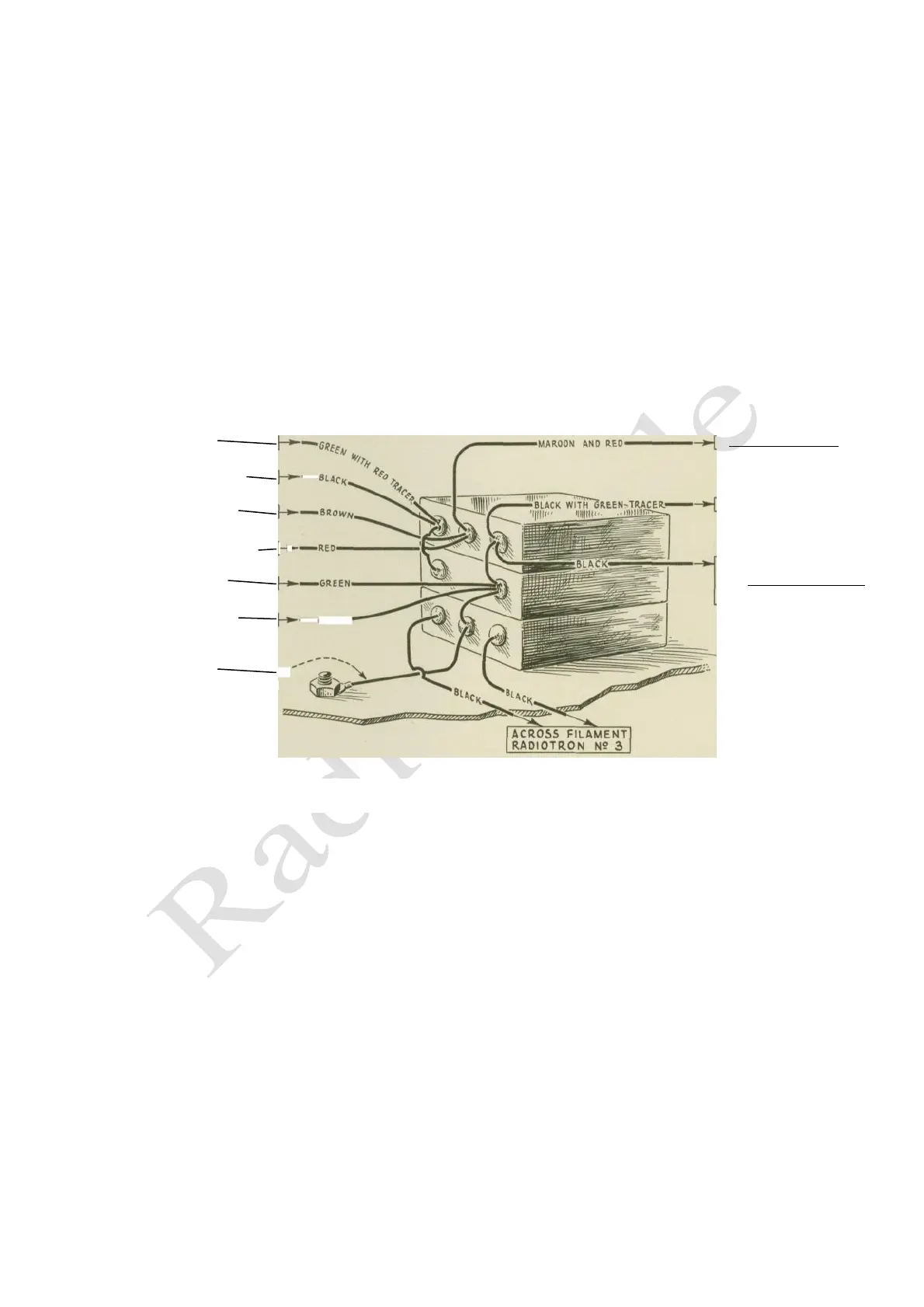
Figure 21 – Connections and color scheme of wiring to by-pass condensers
 Loading...