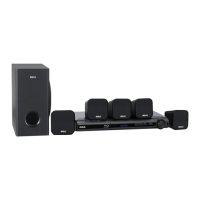
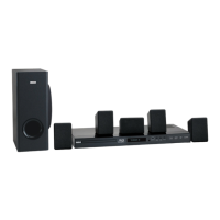
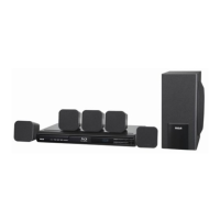
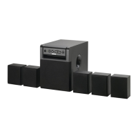
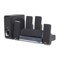
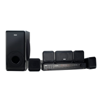
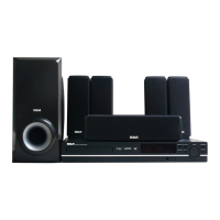
Quick Setup Sheet
RTB1013
Congratulations on purchasing your new RCA product.
Please read these instructions for quick setup sheet on using the product.
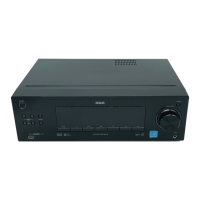
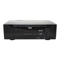
REAR VIEW
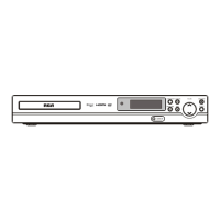
FRONT VIEW
Notes:
1. The AC power plug is
polarized (one blade is
wider than the other) and only fi ts into
AC power outlets one way. If the plug
won’t go into the outlet completely,
turn the plug over and try to insert it
the other way.
2. The HDMI output will give you the
highest quality video connection.
3. To receive clear reception, FM an-
tenna must be hooked up.
Specifi cations and external appearance are
subject to change without advance notice
due to continuous product improvement.
White Speaker Terminals
Co nn ect t he w hite a nd
black wires from Front Left
Speaker to the terminals.
White
Red Speaker Terminals
Connect the red and black
wires from Front Right
Speaker to the terminals.
Red S
Green Speaker Terminals
Connect the green and black
wires from Center Speaker
to the terminals.
LAN (Ethernet) Jack
Use to connect an Ethernet cable (CAT5
or better with RJ45 connector) to the
ETHERNET jack on the back of your
player and to an Ethernet jack on a
broadband hub or router.
Hub or Network Router
Purple Speaker Terminals
Co nn ect t he p ur ple a nd
black wires from Subwoofer
Speaker to the terminals.
HDMI Out Jack
Use to connect an HDMI cable from
HDMI IN jack on the TV to the HDMI
OUT jack on this unit. (See Note 2)
AUDIO OUT Jacks
Use to connect
the AUDIO OUT jacks from the unit to the AUDIO
IN jacks on TV, VCR, Stereo system or other audio component.
VCR Stereo System
TV
Composite Video Out Jack
Use to connect the VIDEO OUT jack on the
back of the unit to the Video IN jack on your
TV so that the video content goes from the
unit to the TV screen.
TV
Blue Speaker Terminals
Connect the blue and
black wires from Rear Left
Speakers (surround sound)
to the terminals.
Gray Speaker Terminals
Connect the gray and black
wires from Rear Right
Speakers (surround sound)
to the terminals.
se to connect an Ethernet cable (
AT5
or better with RJ45 connector
DM
AC Power Cord
Co nn ect t he AC p ow er
plug i nto th e AC power
outlet. (See Note 1)
:
AUDIO IN Jack
Use to connect the AUDIO IN jacks on
the back of the unit to the AUDIO OUT
jacks on TV, VCR, SAT/Cable Box or
others (TV example shown here).
VCR SAT/Cable Box
TV
Component Video Out Jacks
Use to connect
the COMPONENT
VIDEO OUT jacks (Y, P
B
, P
R
) on
the back of the unit to the com-
ponent video IN jacks on your
TV (shown at right) so that the
video content goes from the unit
to the TV screen.
TV
FM Antenna
Connect the FM antenna to the
FM terminal. (See Note 3)
FM ANTENNA
ck of the unit to the AUDI
UT
TV
Optical In Jack
Use to connect the OPTICAL DIGITAL IN jack on the back of
the unit to the OPTICAL OUT jack on TV, VCR, SAT/Cable Box
or other component.
VCR Game Console
TV
OPEN/CLOSE Button
Opens and closes the disc tray.
PLAY/PAUSE Button
Starts/pauses playback.
VOLUME +/- Buttons
Adjusts the volume.
ON/STANDBY Button
Switches the unit on and off.
SOURCE Button
Selects the input sources. Press repeatedly
to select between:
• BD/USB – to watch BD/DVD discs, or
photos and video fi les stored on to a data
disc or USB fl ash drive.
• OPTICAL – to select the digital audio
input.
• AUX – to select the analog audio input.
• TUNER – to listen to the FM radio.
USB Port
For connection of USB fl ash drives.