EasyManuals Logo
Home>Redarc>Battery Charger>BCDC1212T

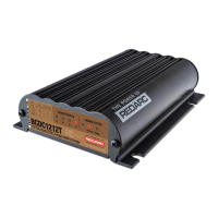
Redarc BCDC1212T User Manual

Redarc BCDC1212T
20 pages
To Next Page IconTo Next Page
To Previous Page IconTo Previous Page
Page #15 background imageLoading...
Page #15 background image
Installation | 15
3.6 STANDARD SETUP
Figure 11: Typical Lad Acid Setup
Standard Trigger
Settings
Leave unconnected
or connect to Ground
Refer to Charging
Prole Select
GREEN
ORANGE
Connect all ground
points to chassis earth
Auxiliary
Battery
Fuse*
BLACK
BROWN
Load
Fuse
Loads
Loads
12 V or 24 V
Start Battery
Bank
Low Voltage
Trigger Settings
to D+ or Vehicle
Ignition
YELLOW
RED
BLUE
Fuse*
Optional
LED with
Resistor**
12V
INPUT
24V
INPUT
OR
Figure 12: Typical LiFePO
4
Setup
Standard Trigger
Settings
Leave unconnected
or connect to Ground
12 V or 24 V
Start Battery
Bank
Fuse*
Join GREEN and ORANGE
for LiFePO
4
Charging
Connect all ground
points to chassis earth
Auxiliary
Battery
Fuse*
BLACK
BROWN
Load
Fuse
Loads
Low Voltage
Disconnect
Low Voltage
Trigger Settings
to D+ or Vehicle
Ignition
RED
BLUE
GREEN
ORANGE
Optional
LED with
Resistor**
12V
INPUT
24V
INPUT
OR
*Fuse ratings as per table on page 5.
**If using an Optional LED, use a standard 12 V LED with an integrated resistor (12 V = 1kΩ or 24 V = 2.2kΩ).
A basic 3 V LED will not operate correctly if installed.

Questions and Answers:

Question and Answer IconNeed help?

Do you have a question about the Redarc BCDC1212T and is the answer not in the manual?

Redarc BCDC1212T Specifications

General IconGeneral
BrandRedarc
ModelBCDC1212T
CategoryBattery Charger
LanguageEnglish

Related product manuals