07
Alarm
—If there is a buzzing sound, the battery is low. The user should reduce the
AC load, charge the battery, and check the DC cable for excessive losses.
Fault LED (Red)
— The red indicator turns on as the inverter shuts down due to overheating,
overload, under voltage, or over voltage.
Immediately turn off all AC appliances if the Fault LED is lit. Allow the inverter to cool
before restart. Make sure that the ventilation vents are not blocked.
If an inverter shutdown was preceded by a buzzing sound, there may be an excessive
load in combination with low voltage or a cable problem.
ON/OFF Switch
— Controls AC output.
AC Outlets
— Up to 15 amps at 110V AC 60 Hz.
Remote Switch Connection
— Insert wired remote switch to the connection port. Set
ON/OFF switch to "remote" position.
Communication Port
—RS485,data transmission.
50Hz/60Hz-
Switches between 50Hz and 60Hz
NOTE
3.
4.
5.
6.
7.
8.
9.
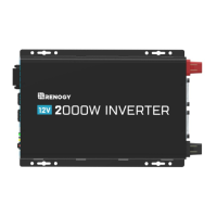
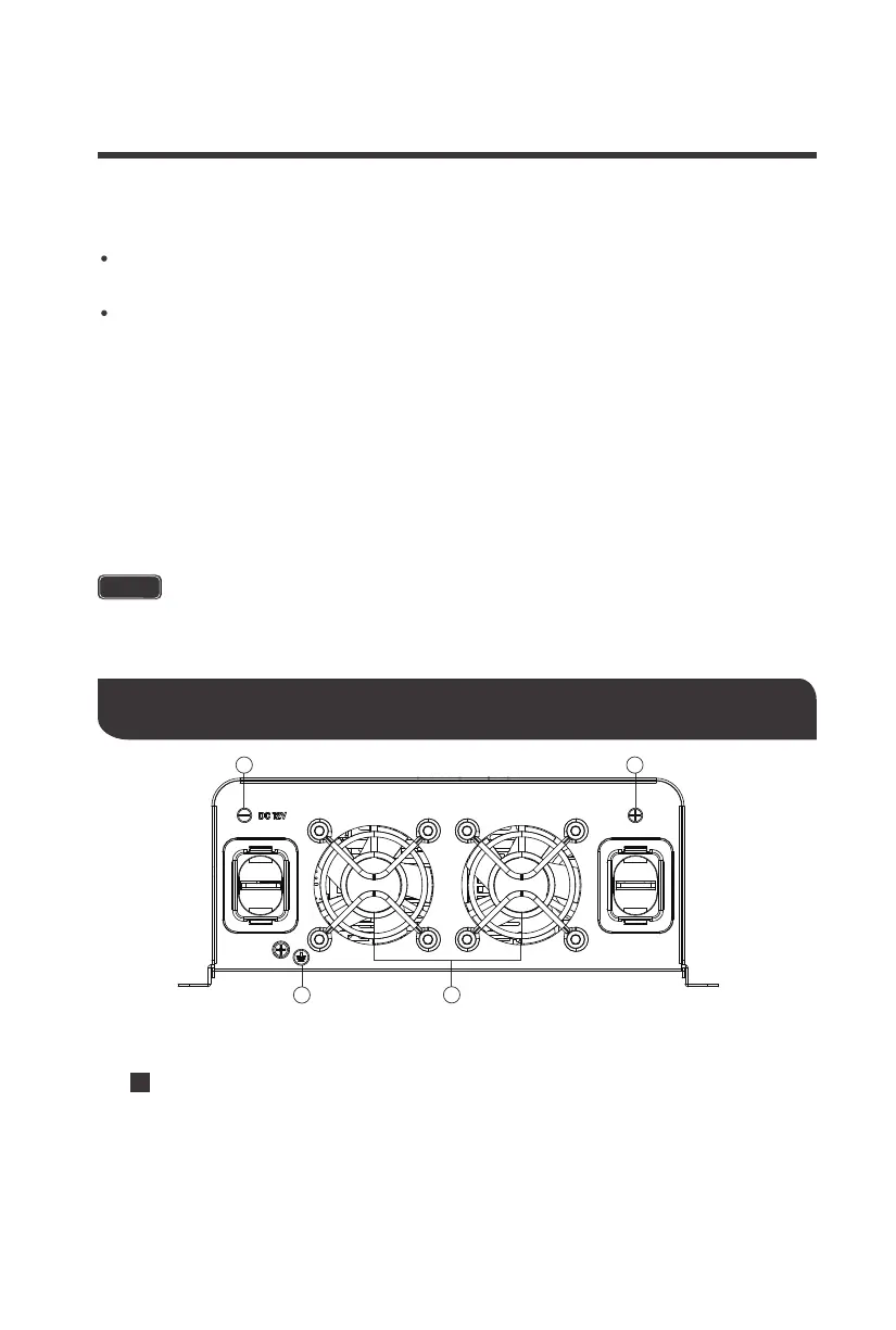
KEY PARTS
1.Positive Terminal
— Positive (+) DC Input (Red)
2.Cooling Fans
— Thermal Sensor controlled
3.Negative Terminal
— Negative (−) DC Input (Black)
4.Ground Terminal
— For insulated safety ground wire.
Figure 3: 2000W Inverter
Identification of Parts (DC Side)
Eco/Nor-
Switches between Energy Saving mode and Normal mode
4
2
3 1
 Loading...