15
4.0 INSTALLATION
< 8 8-15 16-23 24-30 31-38 39-46
6.35 [1/4]
15.88 [5/8] 8 / 0.99 15 / 0.98 9 / 0.97 0 / 0.97 NR NR
7.94 [5/16] 15.88 [5/8] 8 / 0.99 15 / 0.98 15 / 0.97 15 / 0.97 15 / 0.96 15 / 0.95
9.53 [3/8] 15.88 [5/8] 8 / 0.99 15 / 0.99 15 / 0.97 15 / 0.97 15 / 0.96 15 / 0.95
6.35 [1/4] 19.05 [3/4] * 8 / 1.00 15 / 0.99 9 / 0.99 0 / 0.99 NR NR
7.94 [5/16] 19.05 [3/4] * 8 / 1.00 15 / 0.99 15 / 0.99 15 / 0.99 15 / 0.98 15 / 0.98
9.53 [3/8] 19.05 [3/4] * 8 / 1.00 15 / 0.99 15 / 0.99 15 / 0.99 15 / 0.98 15 / 0.98
7.94 [5/16] 15.88 [5/8] 8 / 0.99 15 / 0.97 15 / 0.95 15 / 0.93 9 / 0.91 NR
9.53 [3/8] 15.88 [5/8] 8 / 0.99 15 / 0.97 15 / 0.95 15 / 0.93 15 / 0.91 NR
7.94 [5/16] 19.05 [3/4] 8 / 1.00 15 / 0.99 15 / 0.99 15 / 0.98 9 / 0.97 4 / 0.96
9.53 [3/8] 19.05 [3/4] 8 / 1.00 15 / 0.99 15
/ 0.99 15 / 0.98 15 / 0.97 15 / 0.96
12.7 [1/2] 19.05 [3/4] 8 / 1.00 15 / 0.99 15 / 0.99 15 / 0.98 15 / 0.97 15 / 0.96
9.53 [3/8] 19.05 [3/4] 8 / 0.99 15 / 0.98 15 / 0.97 15 / 0.95 15 / 0.94 15 / 0.92
12.7 [1/2] 19.05 [3/4] 8 / 0.99 15 / 0.98 15 / 0.97 15 / 0.95 15 / 0.94 15 / 0.92
9.53 [3/8] 22.23 [7/8] 8 / 1.00 15 / 0.99 15 / 0.99 15 / 0.98 15 / 0.98 15 / 0.97
12.7 [1/2] 22.23 [7/8] 8 / 1.00 15 / 0.99 15 / 0.99 15 / 0.98 15 / 0.98 15 /
0.97
9.53 [3/8] 19.05 [3/4] 8 / 0.99 15 / 0.96 15 / 0.94 15 / 0.92 NR NR
12.7 [1/2] 19.05 [3/4] 8 / 0.99 15 / 0.96 15 / 0.94 15 / 0.92 NR NR
9.53 [3/8] 22.23 [7/8] 8 / 1.00 15 / 0.99 15 / 0.98 15 / 0.97 14 / 0.96 9 / 0.95
12.7 [1/2] 22.23 [7/8] 8 / 1.00 15 / 0.99 15 / 0.98 15 / 0.97 15 /0.96 15 / 0.95
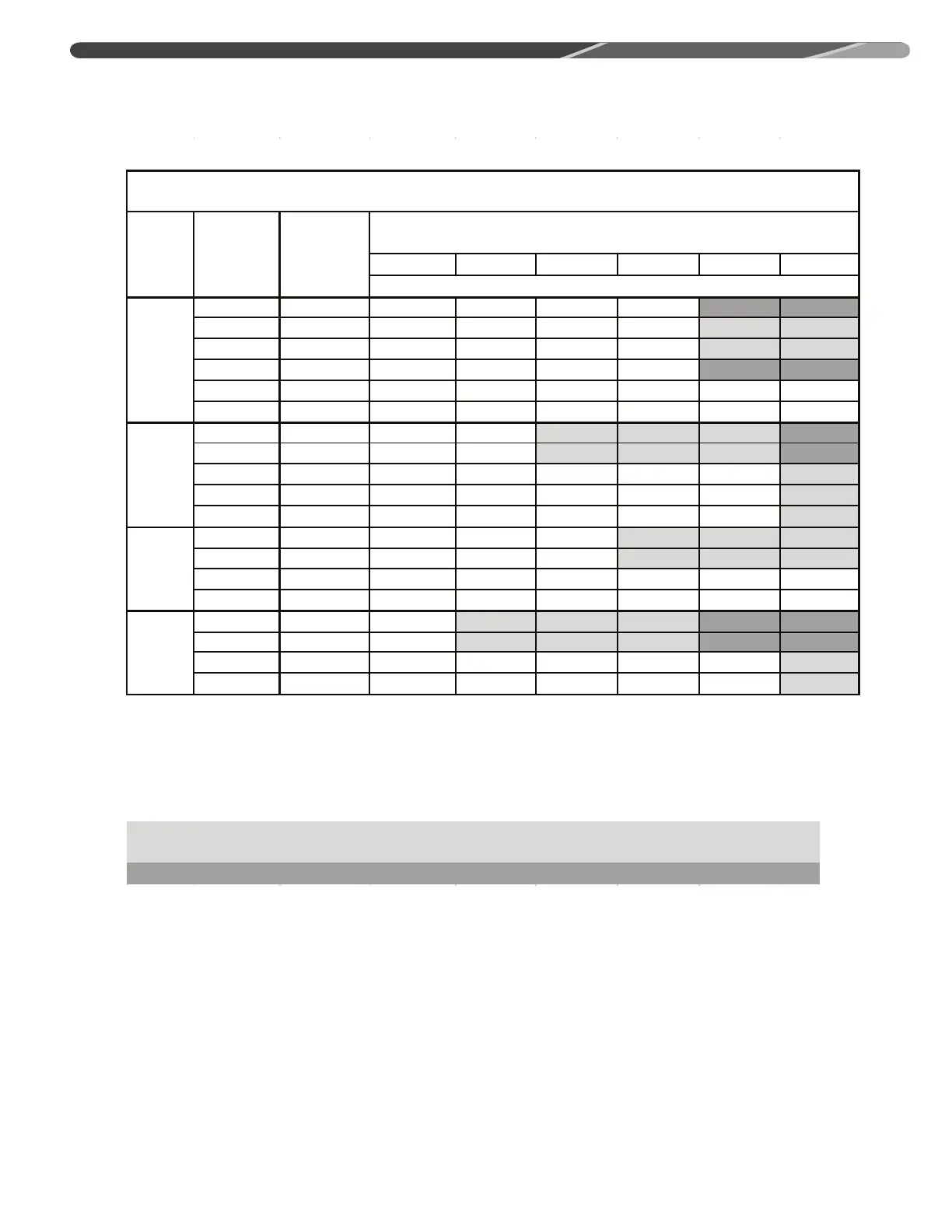
Notes:
1) Do not exceed 46 meters linear line length.
2) Do not exceed 15 meters vercal separaon between indoor and outdoor uni
ts.
unit to assure proper oil return.
4) Always use the smallest liquid line allowable to minimize refrigerant charge.
5) Applicaons shaded in light gray indicate capacity mulpliers between 0.90 and 0.96 which are not
recommended, but are allowed.
6) Applicaons shaded in dark gray are not recommended due to excessive liquid or sucon pressure drop.
7.0 KW
[2.0 Ton]
* SEE
NOTE 3
10.6 KW
[3 Ton]
14.1 KW
[4 Ton]
17.6 KW
[5 Ton]
Table 2B: Refrigerant Line Sizing Chart (Metric Units)
17 SEER 3-Stage Heat Pumps
Unit Size
Allowable
Liquid Line
Size
mm [in.]
Allowable
Vapor Line
Size
mm [in.]
Outdoor Unit ABOVE or BELOW Indoor Unit
Equivalent Length (Meters)
Maximum Vercal Separaon / Capacity Mulplier
3) * 19.05 mm [3/4"] vapor line should only be used for 2 ton systems if outdoor unit is below or at same level as indoor
 Loading...