7
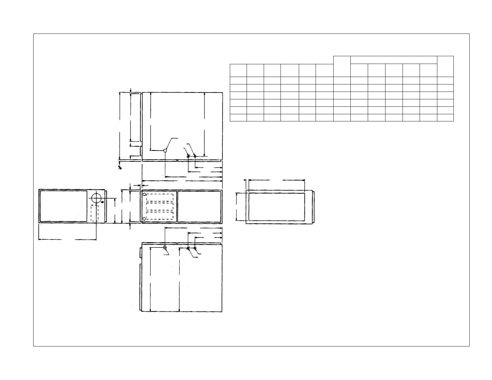
FIGURE 4
REDUCED CLEARANCE (IN.)
Model A B C D E
Left Right
Back Top Front Vent
Ship.
Side Side Wgts.
04, 05 14 12
27
⁄32 10
3
⁄8 ➀ 11
1
⁄2 0 4➁ 0 1 3 6➂ 85 lbs.
06, 07 17
1
⁄2 16
11
⁄32 12
1
⁄8 ➀ 15 0 3➁ 0 1 3 6➂ 105 lbs.
10(A) 17
1
⁄2 16
11
⁄32 12
1
⁄8 ➀ 15 0 3➁ 0 1 3 6➂ 115 lbs.
10(B) 21 19
27
⁄32 13
7
⁄8 ➀ 18
1
⁄2 0 0 0 1 3 6➂ 120 lbs.
12 24
1
⁄2 23
11
⁄32 15
5
⁄8 ➀ 22 0 0 0 1 3 6➂ 140 lbs.
15 24
1
⁄2 23
11
⁄32 15
5
⁄8 ➀ 22 0 0 0 1 3 6➂ 150 lbs.
CLEARANCE TO COMBUSTIBLE MATERIAL (INCHES)
HORIZONTAL “ONLY” MODELS
➀ May require 3( to 4( or 3( or 5( adapter.
➁ May be 0( with type B vent.
➂ May be 1( with type B vent.
TOP VIEW
FRONT
BOTTOM VIEW
LEFT END
RIGHT END
19
⁄32
D
B
A
C
28
1
⁄16
24
1
⁄2
26
13
⁄16
24
11
⁄32
23
17
⁄32
26
5
⁄8
14
3
⁄8
11
1
⁄2
11
1
⁄2
1
1
⁄4
14
3
⁄8
3
⁄4
19
⁄32
19
⁄32
24
11
⁄32
26
5
⁄8
24
7
⁄16
20
34
E
1
3
⁄8 DIA.
7
⁄8 DIA.
7
⁄8 DIA.
S.A.
GAS
CONNECTION
LOW
VOLTAGE
ELECTRICAL
CONNECTION
R.A.
IMPORTANT: This furnace is not approved or recommended for
installation on its back, with access doors facing upwards.
 Loading...