18
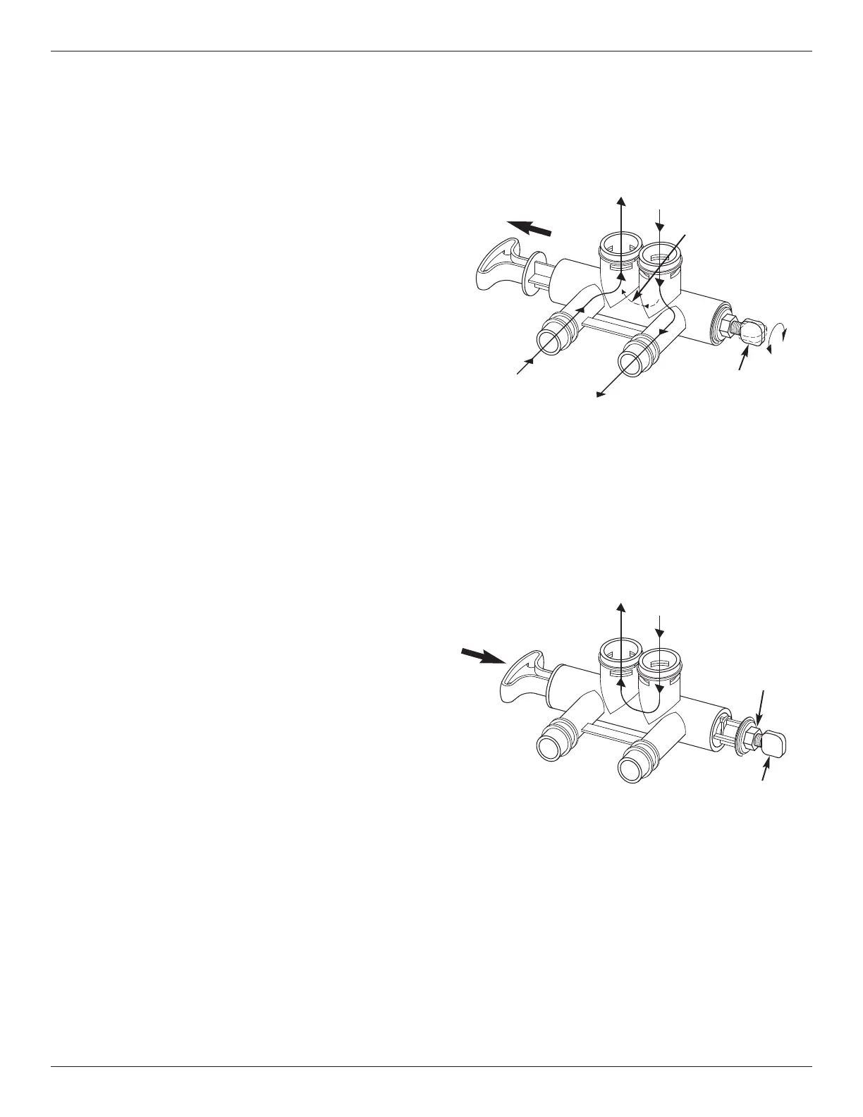
Bypass Blending Valve
The bypass blending valve works as a typical push-
pull bypass valve, but has the added ability to finely
a
djust hardness of the treated water leaving the water
softener. If slightly harder water is desired than is
normally output by the water softener, this bypass
blending valve can divert a small stream of hard
water before it enters the water softener and blend it
with the exiting softened water. The amount of water
diverted is controlled by turning a blend adjusting
knob on the end cap of the valve stem (See Figure
41).
IMPORTANT: Turn the blend adjusting knob by
hand only. Do not overtighten.
1. When the bypass valve is in service position (nor-
mal softener operation), with handle pulled all the
way out (See Figure 41), increase hardness of
treated water by turning the blend adjusting knob
counterclockwise up to 6 turns from the fully
closed position. Before turning the knob, unlock it,
if necessary, by turning the hex nut counterclock-
wise. While adjusting the knob, hold the bypass
valve handle to prevent the stem from rotating.
2. Do not continue to turn the knob counterclockwise
beyond 6 turns from the fully closed position, as
this would eventually pull the screw’s internal o-
rings out of their seat and water would leak from
the bypass valve.
3. Decrease hardness of treated water by turning the
blend adjusting knob clockwise while holding the
bypass handle. Do not overtighten. When the
knob is fully closed, hard water is not being blend-
ed with treated water.
4. Once the desired hardness is achieved, the adjust-
ment knob may be locked in place by tightening
the hex nut clockwise against the end cap using an
adjustable wrench. Hold the bypass valve handle
to prevent the stem from rotating, or else use
another wrench to grip the stem on the flats
between the end cap and the bypass valve body.
Loosen the hex nut (turn it counterclockwise)
before readjusting the hardness or closing the
diversion path for servicing (see next step)
5. If the water softener is to be serviced or discon-
nected from the bypass valve, the blend adjusting
knob must be closed to block the diversion path
and prevent water leaking from the softener valve
inlet of the bypass valve.
FIG. 41
FIG. 42
SERVICE POSITION
(Normal Softener Operation)
BYPASS POSITION
Pull
H
andle
Soft Water
Out
Hard
Water In
Softener
Valve Outlet
Softener
Valve Inlet
Diverted Hard Water
(controlled by blend
adjusting knob)
Blend Adjusting Knob
Turn, by hand only,
counterclockwise to
increase hardness of
treated water (clockwise
to decrease hardness)
Push
Handle
Hard Water
Out
Hard
Water In
Blend Adjusting Knob
If servicing water softener,
turn, by hand only,
clockwise until closed
Hex Nut
Turn clockwise
to lock blend
adjusting knob
(counterclock-
wise to unlock)
 Loading...