24
24
GG
BB
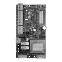
POINT B - SETTINGS
DIP 1 MOTOR ROTATION DIRECTION CHECK (See Point C)
DIP 2 PROGRAMMING (See Point D)
DIP 2-1 PROGRAMMING OF PEDESTRIAN OPENING (See Point E)
DIP 3
ON - Automatic Closing ENABLED
OFF - Automatic Closing DISABLED
DIP 4 ON - Radio receiver STEP BY STEP
OFF - Radio receiver AUTOMATIC
DIP 5 ON - STEP BY STEP
Single pulse contact (K BUTT)
Pedestrian button (PED BUTT)
OFF - AUTOMATIC
Single pulse contact (K BUTT)
Pedestrian button (PED BUTT)
DIP 6 ON - Photocells active only in closing
OFF - Photocells always active
DIP 7 ON - Encoder enabled for PLUS operator
OFF - Encoder disabled
DIP 8 ON - Blinker pre-flashing
OFF - Blinker normal flashing
DIP 9 ON - Low speed in approaching DISABLED
OFF - Low speed in approaching ENABLED
DIP 10 ON - Electronic brake ENABLED (HARD brake, only for FAST
operators)
OFF - Electronic brake DISABLED (SOFT brake, only for FAST
operators)
DIP 11 ON - Gradual start ENABLED
OFF - Gradual start DISABLED
DIP 12 ON - Safety strip self test ENABLED
OFF - Safety strip self test DISABLED
DIP 13 ON - Motor operation control by external power relays (only for
S1/R2 and S1/R4 control boards). Encoder, low speed in
approaching, gradual start and electronic brake features, low
speed and torque regulator will be automatically disabled
regardless their dip-switches and trimmers position.
OFF - Standard motor operation control without power relays
DIP 14 - selection of motor-type (see chart)
DIP 15 - selection of motor-type (see chart)
DIP 16 - selection of motor-type (see chart)
DIP 17 ON - close command after the transit through the photocell
ENABLED
OFF - close command after the transit through the photocell
DISABLED
DIP 18 ON
- Working with motors 120V 60Hz
OFF - Working with motors 230V 50-60Hz
LED WARNINGS
DL1 - programming activated (red)
DL2 - stop contact NC (red)
DL3 - open limit-switch contact (red)
DL4 - close limit-switch contact (red)
DL5 - photocell contact (NC) (red)
DL6 - gate opening (green)
DL7 - gate closing (red)
DL8 - safety strip contact (NC) (red)
DL9 - Encoder output state
FUSES
F1 T100mA Fuse for accessories protection
F2 T5A Fuse for motor windings protection
RELAYS AND MOTOR CONTROL
K1 => Opening command
K2 => Closing command
K3 => Flashing light command
Q5 => TRIAC - Motor command in opening and closing
TORQUE =>TR2 - Electronic regulator for motor torque
Power can be controlled by rotating the TORQUE trimmer – this changes the
output voltage on motor ends (more power is delivered to the motor by rotating
the trimmer clockwise).
Actually, the motor is always turned on at full power regardless the trimmer
position (to guarantee the starting in all the condition) and, then, after
3seconds, the torque control is activated.
LOW SPEED =>TR1 - Electronic regulator for low speed on approach
If DIP9 is turned OFF, the low speed on approach can be controlled by rotating
the LOW SPEED trimmer. The low speed is activated when the gate is 0.50-
0.60 meters away from the complete closed or open position.
ELECTRONIC BRAKE
If DIP 10 is turned ON, the electronic brake will activate upon total opening or
closing.
ELECTRONIC BRAKE (For FAST operators)
If DIP10 is turned ON, a HARD electronic brake will be active.
If DIP10 is turned OFF, a SOFT electronic brake will be active.
GRADUAL START
If DIP11 is turned ON, a gradual movement will be enabled for 1second upon
each starting.
In case of an obstacle is detected by any safety inputs (photocell, safety strip
or encoder), the gradual start is bypassed for the time being to guarantee a
more prompt and safe reaction.
POINT C - MOTOR ROTATION DIRECTION CHECK
This operation is meant to help the installer during the installation and for further
future controls.
1 - Unlock the operator with the Manual Release, slide the leaf open about
halfway and lock the operator again.
2 - Turn
DIP1 to ON position, LED DL1 starts blinking
3 - Press and hold the
PROG.Button, the gate will open or close. Release the
button and the gate will stop. Press and hold again, the gate will move in the
opposite direction.
The S1 control board has two movement leds
- DL6 the GREEN led for OPENING
- DL7 the RED led for CLOSING
When you press and hold the PROG.Button, if the gate opens with the
green led on then you may proceed to step 4.
If the gate moves in the wrong direction compared with the movement leds:
- turn OFF the main AC power
- reverse the V and W motor cables position (the blue motor cable must be
always in the U position)
- reverse the limit switch wires marked LSO and LSC
- turn ON the main AC power and check again the motor direction
4 - After 3seconds (2 for FAST operator) motor starting and for the next 10
seconds (6 for FAST operator) motor working,
the torque control is
automatically activated. Set the motor torque by the TORQUE Trimmer
which varies the output voltage to the head of the motor (turn clockwise to
increase torque).
5 - After other10 seconds (6 for FAST operator) motor working, the
low speed
control
is automatically activated (DIP9 OFF). Set the motor low speed by
the LOW SPEED Trimmer to select the gate leaf low speed in approaching.
6 - Press and hold the PROG.Button to close completely the gate.
Turn DIP1 to
OFF, the RED led DL1 will stop blinking.
CHART 1
DIP 14 DIP 15 DIP16 MOTOR TYPE
OFF OFF OFF K800 - K800 PLUS
ON OFF ON K800 FAST
ON OFF OFF K1400 - K1400 PLUS
OFF ON OFF K2200 - K2200 PLUS
ON ON OFF SUPER 2200
OFF OFF ON SUPER 2200 FAST
OFF ON ON SUPER 3600
ON ON ON SUPER 3600 FAST
 Loading...