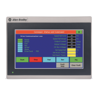
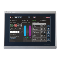
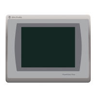
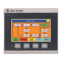
10 PanelView Plus 700 to 1500 and PanelView Plus Compact 1000 Terminals and Display Modules
Publication 2711P-IN001I-EN-P - November 2009
Parts List
These items are shipped with the terminals:
• Power terminal block
• Mounting clips
• FactoryTalk View software preloaded
• Installation instructions and panel cutout template
Required Tools
These tools are required for panel installation:
• Panel cutout tools
• Small, slotted screwdriver
• Torque wrench (lb•in)
Install the Terminal
Before installing the terminal in a panel, review the following topics:
• Mounting clearances
• Panel cutout dimensions
• Product dimensions
Mounting Clearances
Allow adequate clearance around the terminal, inside the enclosure, for adequate ventilation.
Consider heat produced by other devices in the enclosure. The ambient temperature around
the terminals must be between 0…55 °C (32…131 °F).
These minimum clearances are required for ventilation.
• Top clearance: 51 mm (2 in.)
• Bottom clearance: 102 mm (4 in.)
• Side clearances: 25 mm (1 in.)
• Back clearance: 25 mm (1 in.)
Minimum side clearance for insertion of memory card is 102 mm (4 in.).
 Loading...


