2
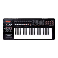
Mar. 2010 A-300PRO, A500PRO, A-800PRO
Table of Contents
Cautionary Notes ..............................................................2
Specifications .....................................................................3
Location of Controls (Top)...............................................4
Location of Controls (Top) Parts List .............................4
Location of Controls (Jack) ..............................................5
Exploded View ..................................................................6
Exploded View Parts List.................................................7
Plain View ..........................................................................8
Plain View Parts List.........................................................9
Where to Apply Tape .....................................................10
Keyboard Parts List (A-800PRO) ..................................11
Keyboard Parts List (A-500PRO) ..................................12
Keyboard Parts List (A-300PRO) ..................................13
Wiring Diagram...............................................................14
Block Diagram .................................................................16
Parts List ...........................................................................18
Verifying the Version Number......................................20
Data Backup and Restore Operations ..........................20
Performing a Factory Reset............................................20
Updating the System ......................................................21
Test Mode.........................................................................21
Cautionary Notes
Before beginning the procedure, please read
through this document. The matters described may
differ according to the model.
Back Up User Data!
User data may be lost during the course of the procedure. Refer to “Data
Backup and Restore Operations” (p. 20) in the Service Notes and save the
data. After completing the procedure, restore the backed-up data to the
product.
Part Replacement
When replacing components near the power-supply circuit or a heat-
generating circuit (such as a circuit provided with a heat sink or including a
cement resistor), carry out the procedure according to the instructions with
respect to the part number, direction, and attachment position (mounting so as
to leave an air gap between the component and the circuit board, etc.).
Parts List
A component whose part code is ******** will not be supplied as a service part
because one of the following reasons applies.
• Because it is supplied as an assembled part (under a different part code).
• Because a number of circuit boards are grouped together and supplied as
a single circuit board (under a different part code).
• Because supply is prohibited due to copyright restrictions.
• Because reissuance is restricted.
• Because the part is made to order (at current market price).
• Because it is carried in electronic data on the Roland web site.
• Because it is a package or an accessory irrelevant to the function
maintenance of the main body.
• Because it can be replaced with an article on the market. (battery or etc.)
 Loading...