SERVICE NOTES
Unauthorized copying or transferral, in whole or in part, of this manual is prohibited.
Copyright © 1998 ROLAND DG CORPORATION
Windows is registered trademark or trademark of Microsoft Corporation in the United States and/or other countries.
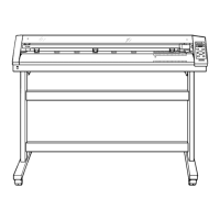
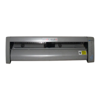
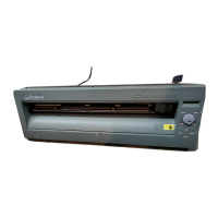
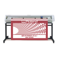
CM-500 / 400 / 300
R1-980615Printed in Japan
1 Structure & Spare Parts
1-1 COVERS .......................................................................................1
1-2 FRAME ..........................................................................................2
1-3 X/Y DRIVE UNIT ...........................................................................4
1-4 CARRIAGE ...................................................................................5
1-5 CHASSIS ......................................................................................6
1-6 PINCH ROLLER ............................................................................7
1-7 OTHERS .......................................................................................8
1-8 STAND ..........................................................................................8
2 Electrical Section
2-1 WIRING MAP ................................................................................9
2-2 MAIN BOARD ASS'Y .................................................................. 10
2-3 POWER BOARD ASS'Y .............................................................. 14
2-4 OTHER CIRCUIT BOARDS ........................................................ 16
3 Replacement of Main Parts
3-1 PEN CARRIAGE ASSEMBLY_REMOVING ...............................17
3-2 CARRIAGE WIRE_REMOVING .................................................20
3-3 PINCH ROLLER_FIXING ............................................................ 23
3-4 CUTTER PROTECTION_FIXING ............................................... 23
4 Adjustment
4-1 Special Tool ................................................................................ 25
4-2 Service Mode ..............................................................................26
4-3 HOW TO UPGRADE FIRMWARE .............................................. 28
4-4 TOOL HEIGHT ADJUSTMENT ................................................... 29
4-5 SPACER BED ADJUSTMENT .................................................... 31
4-6 TOOL PRESSURE ADJUSTMENT ............................................ 34
4-7 WIRE TENSION ADJUSTMENT................................................. 37
4-8 MOTOR BALANCE ADJUSTMENT ............................................ 39
4-9 CALIBRATION ............................................................................ 42
4-10 SOFTLANDING ADJUSTMENT ................................................. 45
4-11 SEPARATING KNIFE ADJUSTMENT ........................................ 48
5 Supplemental Information
5-1 OPERATIONAL SEQUENCE ..................................................... 51
5-2 SENSOR MAP ............................................................................ 52
6 Troubleshooting
6-1 TROUBLESHOOTING ................................................................ 53
7 Supplement
7-1 MAINTENANCE CHECK LIST .................................................... 55
7-2 INSTALLATION CHECK SHEET ................................................ 56
7-3 SPECIFICATIONS ...................................................................... 56
Contents
Structure & Spare Parts
Electrical Section
Replacement of Main Parts
Adjustment
Supplemental Information
Troubleshooting
Supplement
1
2
3
4
5
6
7
First Edition
CM-500/400/300 '98.Jun.DE1