SERVICE NOTES
Unauthorized copying or transferral, in whole or in part, of this manual is prohibited.
Copyright © 1998 ROLAND DG CORPORATION
Windows is registered trademark or trademark of Microsoft Corporation in the United States and/or other countries.
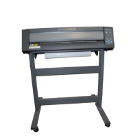
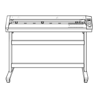
PC-60
R1-980203
First Edition
PC-60 '98.Jan.DE1
Printed in Japan
1 Structure & Spare Parts
1-1 COVERS .......................................................................................1
1-2 FRAME (1) ....................................................................................2
1-3 FRAME (2) ....................................................................................4
1-4 CHASSIS ......................................................................................6
1-5 THERMAL CARRIAGE .................................................................7
1-6 TOOL CARRIAGE .........................................................................7
1-7 STAND ..........................................................................................8
1-8 ACCESSORIES ............................................................................8
2 Electrical Section
2-1 WIRING MAP ................................................................................9
2-2 MAIN BOARD ASS'Y .................................................................. 10
2-3 OTHER CIRCUIT BOARDS ........................................................ 17
3 Replacement of Main Parts
3-1 HEAD CARRIAGE ASSEMBLY_QUICK REPLACEMENT ......... 19
3-2 HEAD CARRIAGE ASSEMBLY_REPLACEMENT .....................22
3-3 TOOL CARRIAGE ASSEMBLY_REPLACEMENT .....................25
3-4 PLATEN DAMPER_REPLACEMENT ......................................... 26
3-5 HEAD LEVER_FIXING ............................................................... 27
3-6 CARTRIDGE HOLDER ARM_REPLACEMENT .........................29
3-7 PINCH ROLLER_REPLACEMENT ............................................. 32
3-8 WIRE_REPLACEMENT .............................................................. 35
3-9 MOTOR_FIXING .........................................................................38
4 Adjustment
4-1 Special Tool ................................................................................ 39
4-2 Service Mode .............................................................................. 40
4-3 Factory Mode .............................................................................. 41
4-4 Faunction Mode .......................................................................... 43
4-5 HOW TO UPGRADE FIRMWARE .............................................. 45
4-6 TOOL HEIGHT ADJUSTMENT ................................................... 46
4-7 TOOL PRESSURE ADJUSTMENT ............................................ 48
4-8 HEAD VOLTAGE ADJUSTMENT ............................................... 51
4-9 AUTO THERMAL HEAD DENSITY ADJUSTMENT ................... 53
4-10 MANUAL THERMAL HEAD DENSITY ADJUSTMENT .............. 57
4-11 HEAD POSITION ADJUSTMENT 1 ............................................ 61
4-12 HEAD POSITION ADJUSTMENT 2 ............................................ 63
4-13 PRINT/CUT OFFSET ADJUSTMENT .........................................65
4-14 CARTRIDGE POSITION ADJUSTMENT .................................... 67
4-15 CMYK SENSING CHECK ........................................................... 70
4-16 GRIT COMPENSATION ............................................................. 72
4-17 WIRE TENSION ADJUSTMENT .................................................75
4-18 STITCHING ADJUSTMENT ........................................................ 77
4-19 GRIT ECCENTRICITY ADJUSTMENT .......................................80
5 Supplemental Information
5-1 OPERATIONAL SEQUENCE ..................................................... 85
5-2 SENSOR MAP ............................................................................86
6 Troubleshooting
6-1 PRINTING ................................................................................... 87
6-2 CUTTING .................................................................................... 89
6-3 OTHERS .....................................................................................91
7 Supplement
7-1 MAINTENANCE CHECK LIST .................................................... 93
7-2 USER’S DIP SW SETTING .........................................................94
7-3 LINE SPACING ADJUSTMENT MODE ...................................... 95
7-4 SPECIFICATIONS ...................................................................... 96
Contents
Structure & Spare Parts
Electrical Section
Replacement of Main Parts
Adjustment
Supplemental Information
Troubleshooting
Supplement
1
2
3
4
5
6
7
SERIAL NUMBER
This service note applies directly to the PC-60
with serial numbers ZK60950 and above.