Accessing the Accessing the
video manualvideo manual
Accessing the Accessing the TD-02TD-02
Owner’s ManualOwner’s Manual
You can scan the
following 2D code to see
a quick start video. This
video explains the steps
for assembly.
Refer to the “Owner’s
Manual” (Roland website)
for details on how to use
TD-02. Use this 2D code
to access the website.
1
2
Drum stand
Setup Guide
© 2022 Roland Corporation
Before using this unit, carefully read “USING THE UNIT SAFELY” and “IMPORTANT NOTES” (in the leaet “USING THE UNIT SAFELY” and in the TD-02KV Setup Guide). After reading, keep the document(s)
where it will be available for immediate reference.
Check the included items
As soon as you open the package, check to see that all items are included. If anything is missing, please contact your dealer.
Assemble the drum stand
* If you will be using this drum stand for an extended period of time in the same location, we recommend that you use a drum mat (TDM series) made by Roland
to prevent the rubber feet from soiling the surface on which they are placed.
* The drum stand assembly procedure is for right-handed players. If you want to set up the stand for left-handed players, refer to “Assembly for left-handed
players” in the lower right.
For a left-handed setup
Assemble the drum stand as described in
“Assembly for left-handed players” in the “
2
Assemble the drum stand” section, and then
attach the parts and connect the cables as
shown in the illustration at right.
à When you’ve nished making connections, turn on the power as
described in “ Quick Start”, and verify that you can hear sound.
This completes assembly and connections.
* Adjust the position and height of the pads and
pedals according to your build and preferences,
so that they are easy to play.
CY-5CY-5
CY-5CY-5
CY-5CY-5
PD-4PD-4
PD-4PD-4
PD-4PD-4
PDX-8PDX-8
TD-02TD-02
Hi-hat control Hi-hat control
pedalpedal
Kick pedalKick pedal
1.
Assembling the left and right arm sections
Right armRight arm
Left armLeft arm
* Lay the left and right arm sections on the oor while assembling them.
Left arm section
1–1. Use the drum key to loosen the bolt of the left leg
4
holder, and insert the left arm
3
.
3
Left arm
Left
leg
4
Drum
key
1–2. Once the pipe is fully inserted, rmly tighten the bolt
with the drum key.
* Insert the left arm
3
so that the bolt on the holder faces towards
the player, as shown in the illustration.
Left arm
3
Bolt
Right arm section
1–3. Use the drum key to loosen the bolt of the right leg
7
,
and insert the right arm
6
.
1–4. Once the pipe is fully inserted, rmly tighten the bolts (2)
with the drum key.
Right arm
Right
leg
7
6
Bolt
2.
Attaching the left/right arm sections onto the
center frame
Right armRight arm
Left armLeft arm
Center Center
frameframe
2–1. Use the drum key to loosen bolt of holder A attached
to the left-side pipe (with two holders) on the left side
of the center frame
5
, and insert the left arm
3
of the
assembly you created in step 1 into holder A.
Holder A
Bolt
Left arm
3
Center frame
5
2–2. Once the pipe is fully inserted, rmly tighten the bolt
with the drum key.
Bolt
2–3. Use the drum key to loosen bolt of holder B, and insert
the right arm
6
of the assembly you created in step 1
into holder B of the center frame
5
.
Right arm
6
Holder B
Bolt
2–4. Once the pipe is fully inserted, rmly tighten the bolt
with the drum key.
Bolt
3.
Attaching the snare pipe
Snare pipeSnare pipe
3–1. Use the drum key to loosen the bolt of holder C, and
insert the snare pipe
9
into holder C of the center frame
5
.
3–2. Once the pipe is fully inserted, rmly tighten the bolt
with the drum key.
* Insert the snare pipe that’s not tted with a cap into holder C.
Snare pipe
Holder C
Cap
Bolt
9
4.
Adjusting the vertical pipes
4–1. Place the center frame
5
upright, then loosen the hand
knobs (2) of holders A and B. Next, spread open the
pipes at left and right.
4–2. Adjust the angle so that the drum stand can stand
up by itself, and then tighten the hand knobs
(2) that you loosened.
4–3. Make sure that the four vertical pipes remain fully
upright, and that the left/right arms are fully horizontal.
If the stand is wobbling, loosen the bolts for the left leg
4
and
right leg
7
holders and adjust the height. After adjusting the
height, tighten the bolts on the holders.
Holder bolts
Hand knobs of
holders A and B
5.
Attaching the pad mounts
Center frame/snare pipe
5–1. Attach the U-shaped pipe holders
5
onto the top of the
center frame
10
, and tighten the respective hand knobs.
U-shaped pipe holder
Hand knobs
10
5–2. Attach the U-shaped pipes
8
onto the U-shaped pipe
holders
10
, and rmly tighten the respective hand
knobs.
U-shaped pipes
8
Hand knobs
Drum
key
Bolt
5–3. Attach the snare holder
11
to the snare pipe
9
, and
tighten the hand knob.
NOTE
The tip of the snare holder is sharp. Handle it with care.
Snare holder
Hand knob
11
Right arm
5–4. Attach the U-shaped pipe holder
10
to the right leg
7
and tighten the hand knob.
U-shaped pipe holder
Hand knob
10
5–5. Attach the U-shaped pipe
8
onto the U-shaped pipe
holder
10
, and use the drum key to rmly tighten the
bolt.
Bolt
U-shaped pipe
8
10
U-shaped pipe holder
6.
Attaching the tom pads (T1, T2), cymbal rod
and hi-hat rod
6–1. Attach the toms (2) onto the U-shaped pipe
8
on the
top of the center frame
5
.
U-shaped
pipe
Bolt
Drum
key
8
T1T1 T2T2
6–2. Attach the cymbal rod holders
12
(2) onto the U-shaped
pipes
8
on the top of the center frame
5
.
6–3. Insert the rods into the holders, and adjust the position
and direction of all parts as shown in the illustration to
complete the setup.
Hi-hat rod
Cymbal rod
2
1
NOTE
• Be careful not to get your ngers pinched between the drum stand and the movable parts when you set up or adjust the drum stand.
If using this in a location where children are present, be sure to provide adult supervision or guidance.
• Be sure that there is plenty of space to safely assemble this instrument.
• Do not use a power tool (e.g., an electric screwdriver) to assemble this instrument. Doing so may damage the screws.
• Do not overtighten the bolts.
• Be careful not to get grease from the bolts on your hands or other items.
Cabling diagram for the dedicated
connection cable
(As seen from the back)
4
Connection procedure
Connect the pads to the drum sound module (TD-02)
* Insert the plug rmly,
making sure it’s all the
way in.
1. Connect the dedicated
connection cable to the drum
sound module as shown in the
illustration below.
Insert the connector all the
way, then turn the knobs to
lock it in place.
2. Labels indicating the pad to be
connected are attached to the
dedicated connection cable.
Connect the cables by referring
to the illustration at right.
* Fasten the cables so that they will not obstruct your playing; use cable clips
13
and cable ties
14
.
We recommend attaching the clips in the locations shown with a
.
Make sure to wrap the cable ties around the pipes.
Cabling diagram for the dedicated connection cable
(as seen from the back)
3
Attach the parts
NOTE
Be careful not to get your ngers pinched by the movable parts when you operate the drum
sound module holder, the hi-hat control pedal, the kick pedal or the cymbals. If using this in
a location where children are present, be sure to provide adult supervision or guidance.
Adjust the height of the
rod so that the highest
point of the cymbal is less
than 1.2 meters.
Attach the cymbal
rods so that they
face straight up, to
prevent the drum
stand from falling
over.
Adjusting the position of the cymbal
TD-02KV
Label
Assembly for left-handed players
If you want to use a left-handed setup, assemble the stand as follows.
• Detach holder C (for the snare) that’s on the left side of the center
frame
5
, and attach it onto the right side. Attach the snare pipe
9
onto holder C, and then attach the snare holder
11
.
• Swap the positions of the left arm
3
and left leg
4
with the right arm
6
and right leg
7
. Attach the arm so that the hi-hat rod holder bolt
faces inwards (towards the player), and then attach the hi-hat rod
2
.
• Attach the U-shaped pipe holder
10
and U-shaped pipe
8
on the
left-side leg.
Right legRight leg
Hi-hat rodHi-hat rod
Left legLeft leg
9
7
4
8
U-shaped U-shaped
pipepipe
Snare pipeSnare pipe
9
No. Name Quantity
1
Cymbal rod 2
2
Hi-hat rod 1
3
Left arm 1
4
Left leg 1
5
Center frame 1
6
Right arm 1
7
Right leg 1
8
U-shaped pipe 3
9
Snare pipe 1
10
U-shaped pipe holder 3
11
Snare holder 1
12
Cymbal rod holder 2
13
Cable clip 4
14
Cable tie 2
11
9
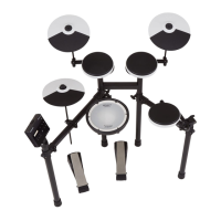
Drum sound module, pads, other items
Â
Hi-hat control pedal
(FD-1)
Â
Kick pedal (KT-1)
Â
Cymbal pad for hi-hat/ride/crash
(CY-5 x 3)
Â
Dedicated
connection cable
Â
AC adaptor
Â
V-Pad for snare
(PDX-8)
Â
Pad for tom
(PD-4 x 3)
Â
Drum sound
module
(TD-02)
Â
Drum sound
module holder
Â
Drum key
* See “Hi-hat control pedal, kick pedal” on the back
side for how to distinguish between the pedals.
OK Not
OK
* To prevent the drum stand from
tipping over, do not position the
stand leg pipes at the two ends
more than 1.2 meters apart.
1.2 m
1. Use the bolt for the drum sound module holder to attach the drum
sound module to the holder.
Drum sound module holder
Bolt
2. Loosen the bolt of the drum sound module holder, attach the top part of the
left leg holder and tighten the bolt.
Attaching the drum sound module (TD-02)
Attaching the crash cymbal/ride cymbal (CY-5)
Insert the cymbal onto the top of the cymbal mount.
1.2 m
Not OK
OK
1. Insert the cymbal so that the stopper (convex portion) on the hi-hat
rod ts into the concave part on the bottom of the cymbal.
2. Tighten the cymbal nut enough to prevent the pad from wobbling
when you strike it.
Attaching the hi-hat (CY-5)
“Roland” logo on the
farther side
Rotation
stopper
(convex
portion)
Cymbal nut
Attaching the toms (PD-4)
U-shaped
pipe
Bolt
Drum
key
* When attaching the PDX-8 (snare), refer to “About
the memory clamp” on the other side.
Attaching the snare drum (PDX-8)
Loosen
Tighten
Snare holder
Knob
Hi-hat Hi-hat
control control
pedalpedal
Kick pedalKick pedal
PD-4PD-4
((T1T1))
PD-4PD-4
(T2)(T2)
PD-4PD-4
((T3T3))
PDX-8PDX-8
((SNRSNR))
CY-5CY-5
((RDRD))
CY-5CY-5
(CR1)(CR1)
CY-5CY-5
((HHHH))
TD-02TD-02
4
1
2 3 6
8
10
12
13
14
5
7
CR2
HH
SNR
KIK
HHC
T3
RD
CR1
T2 T1
TD-02
“CR2” is not used. You can use a
separately sold cymbal set (OP-
TD1C) to add more cymbals. If
you are not adding this, leave
the cap attached. Fasten it so
that it does not obstruct your
performance.
“CR2” is not used. You can use a separately sold
cymbal set (OP-TD1C) to add more cymbals. If you
are not adding this, leave the cap attached. Fasten
it so that it does not obstruct your performance.
T2T1
T3
HH
SNR
TD-02
KIK
RD
CR1
HHC
CR2