10 – English
FEATURES
The following tools (not included) are needed for making adjustments:
TOOLS NEEDED
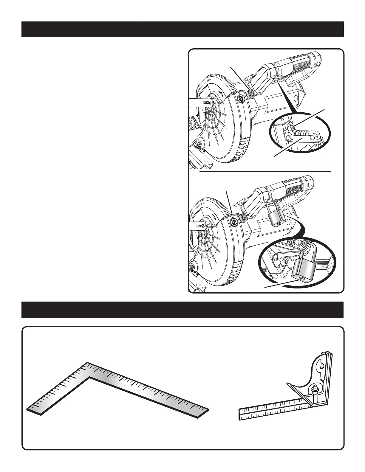
FRAMING SQUARE
COMBINATION SQUARE
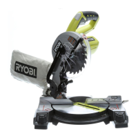
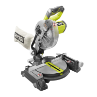
Fig. 4
Fig. 3
SPINDLE
LOCK BUTTON
TRIGGER
LOCKOUT
LEVER
SWITCH TRIGGER
PAD LOCK
POSITIVE STOPS ON MITER TABLE
Positive stops have been provided at 0°, 15°, 22.5°, 31.6°,
and 45° on both the left and right side of the miter table.
SELF-RETRACTING LOWER BLADE GUARD
See Figure 3.
The lower blade guard is made of shock-resistant, see-
through plastic that provides protection from each side of
the blade. It retracts over the upper blade guard as the saw
is lowered into the workpiece.
SPINDLE LOCK BUTTON
See Figure 3.
The spindle lock button locks the spindle, stopping the
blade from rotating. Depress and hold the lock button while
installing, changing, or removing the blade.
SWITCH TRIGGER
See Figure 3.
The saw will not start until you depress the trigger lockout
lever and squeeze the switch trigger. To prevent unauthorized
use of the compound miter saw, remove the battery pack
from the tool and lock the switch in the off position. To lock
the switch, install a padlock (not included) through the hole in
the switch trigger and make certain the switch is inoperable.
If the switch is still operable with the padlock installed, a
padlock with a larger shackle diameter must be used. Store
the padlock key in another location.
LOWER
BLADE GUARD
 Loading...