ASSEMBLY
10
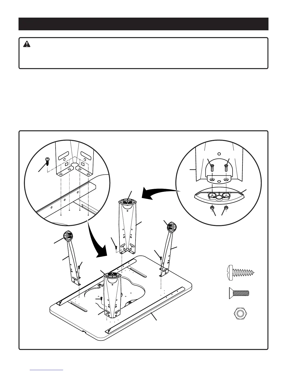
Fig. 2
3. Attach legs (D) securely to table top with 16 pan head
screws (AB). Use a #3 Phillips screwdriver to keep from
stripping the screw heads.
WARNING:
The router or router table should never be connected to a power supply when you are assembling parts, making
adjustments, installing or removing cutters, cleaning, or when not in use. Disconnecting the router and router table
will prevent accidental starting that could cause serious personal injury.
ASSEMBLING THE ROUTER TABLE
See Figure 2
1. Place router table top (C) upside-down on a flat surface.
Take care not to scratch the table top surface.
2. Place footpads (V) on the bottom of table legs (D) and
fasten together using 8 countersink screws (AK) and 8
hex nuts (AL) provided. Use a #1 Phillips screwdriver to
keep from stripping the screw heads.
AB (16)
AK (8)
AL (8)
AB
AB
AB
AB
D
V
D
AL
V
AK
AK
C
V
D
AB
D
V
D
V
Bdal 6146.461 3Sprachen 04.06.2005 11:58 Uhr Seite 10
 Loading...