Do you have a question about the Samsung RF261BEA and is the answer not in the manual?
| Total Capacity | 25.5 cu. ft. |
|---|---|
| Refrigerator Capacity | 17.5 cu. ft. |
| Freezer Capacity | 8.0 cu. ft. |
| Energy Star Certified | Yes |
| Ice Maker | Yes |
| Water Dispenser | Yes |
| Cooling System | Twin Cooling Plus |
| Type | French Door |
| Counter Depth | No |
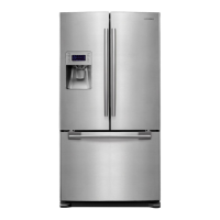
| Color | Stainless Steel |
Warning for technicians regarding potential risks, personal injury, and property damage.
Contact details for technical assistance and access to support portals.
Procedure to activate Force Mode for rapid cooling by pressing specific buttons.
Instructions for initiating the self-diagnostic function to detect errors.
Steps to enter Load Mode for specific operational checks and performance evaluation.
Procedure to activate and cancel the Cooling Off mode for the refrigerator.
Procedure to check the DC voltage of the fan circuit for proper operation.
Details on the ice production completion process based on thermistor readings.
Steps to activate and perform the Ice Maker test mode for harvesting and water supply.
Explanation of how the freezer temperature is managed by the ice maker's status.
Troubleshooting for Freezer Sensor errors related to separation or temperature.
Troubleshooting for Fresh Food Sensor errors related to separation or temperature.
Troubleshooting for Freezer Defrost Sensor errors, including separation and temperature.
Troubleshooting for Fresh Food Defrost Sensor errors, including separation and temperature.
Troubleshooting for Ambient Sensor errors.
Troubleshooting for Flex Room Sensor errors.
Troubleshooting for Ice Maker sensor errors.
Troubleshooting for Humidity Sensor errors.
Troubleshooting for Freezer Fan errors, including signal and motor issues.
Troubleshooting for Fresh Food Fan errors, including signal and motor issues.
Troubleshooting for Freezer Defrost errors, including heater and fuse issues.
Troubleshooting for Fresh Food Defrost errors, including heater and fuse issues.
Troubleshooting for repeated Ice Maker function errors.
Troubleshooting for Damper Heater errors, including separation and short circuits.
Troubleshooting for Freezer Ice Pipe Heater errors, including wiring issues.
Troubleshooting communication errors between the main MICOM and the panel.
Troubleshooting issues when the compressor fails to start.
Troubleshooting errors related to the Intelligent Power Module (IPM).
Troubleshooting abnormal current detection at the compressor.
Troubleshooting for motor locked or over RPM conditions.
Troubleshooting low voltage errors related to the compressor.
Troubleshooting over voltage errors related to the compressor.
Indicators for RF compartment fan operation speed (High/Low).
Indicator for the operation of the RF compartment defrost heater.
Indicates the refrigerator is in start mode after initial power-up.
Indicator showing when the compressor is actively operating.
Indicators for FZ compartment fan operation speed (High/Low).
Indicator for the operation of the FZ compartment defrost heater.
Indicators for compressor fan operation speed (High/Low).
Indicator for the operation of the French heater.
Indicator for the pantry room damper being open.
Indicates when the ice maker bucket is full.
Layout and function of connectors for AC loads, water solenoids, and heaters.
Layout and function of connectors for damper heater, damper motor, and step valve.
Layout and function of connectors for display LEDs, sensors, and switches.
Layout and function of connectors for inverter signals and compressor outputs.
Layout and function of connectors for various sensors and switches.
Layout and function of connectors related to the ice maker system.
Wiring diagram showing connections between the panel LED board and the main PBA.
Wiring details for AC loads, heaters, and solenoid valves.
Wiring diagram for fan motors, ice maker, and various sensors.
Wiring connections for the inverter, compressor, and related components.
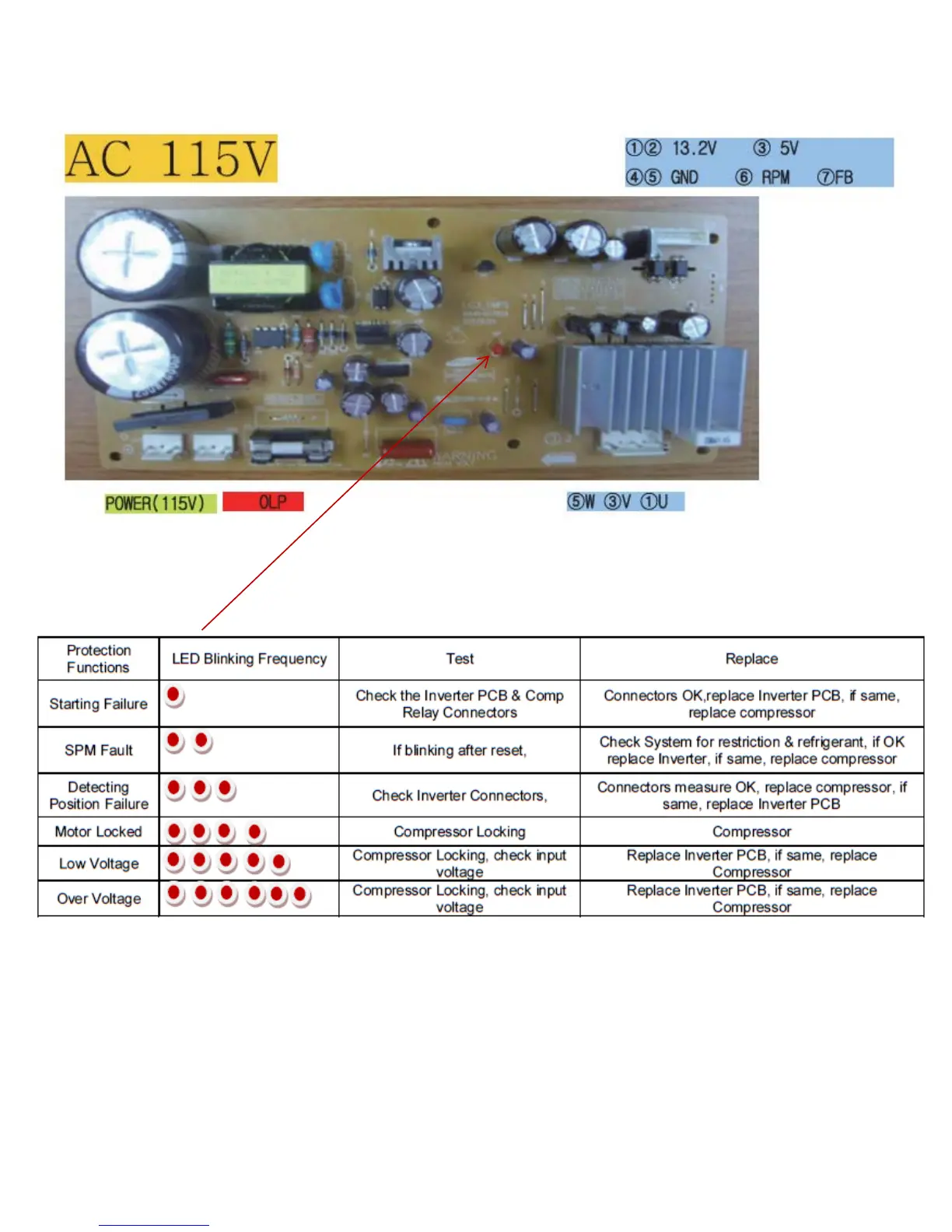
Troubleshooting steps for starting failure, involving inverter PCB and relay connectors.
Procedure to check the inverter PCB and compressor system for SPM faults.
Troubleshooting for detecting position failure by checking inverter connectors.
Troubleshooting steps for motor locked conditions, checking compressor and inverter.
Troubleshooting low voltage errors by checking compressor locking and input voltage.
Troubleshooting over voltage errors by checking compressor locking and input voltage.