Adjustments
-12-
HORIZONTAL ADJUSTMENT
HIGH-VOLTAGE CONFIRMATION
VERTICAL ADJUSTMENT
HORIZONTAL CENTRING ADJUSTMENT
(1) Receive circular pattern and set screen mode to “FULL”.
(2) Enter to the service mode and select mode “Image”, and
select item No. 02 “Image 02 P H-P”.
(3) Press the Level up (+) or Level down (
-
) button to adjust the
horizontal centre.
VER
TICAL CENTRING ADJUSTMENT
(1) Receive circular pattern and set screen mode to “FULL”.
(2) Enter to the service mode and select mode “Image”, and
select item No. 01 “Image 01 P V-C”.
(3) Press the Level up (+) or Level down (
-
) button to adjust the
vertical centre.
Horizontal centre
HORIZONTAL
WIDTH ADJUSTMENT
(1) Receive circular pattern and set screen mode to “FULL”.
(2) Enter to the service mode and select mode “Image”, and
select item No. 06 “Image 06 P H-S”.
(3) Press the Level up (+) or Level down (
-
) button to adjust the
horizontal width.
Note: +B (+150V) Voltage Check and Grayscale Adjustment must
be completed before attempting High Voltage Check.
(1) Connect high-voltage meter to the anode of CRT and the
ground.
(2) Receive circular pattern and set screen mode to “FULL”.
(3) Set controls for brightness and contrast to maximum.
(4) Confirm high voltage is within 29.5 KV and 31.5 KV at maxi
mum beam current.
VERTICAL HEIGHT ADJUSTMENT
(1) Receive circular pattern and set screen mode to “FULL”.
(2) Enter to the service mode and select mode “Image”, and
select item No. 05 “Image 05 P V-A”.
(3) Press the Level up (+) or Level down (
-
) button to adjust the
vertical height.
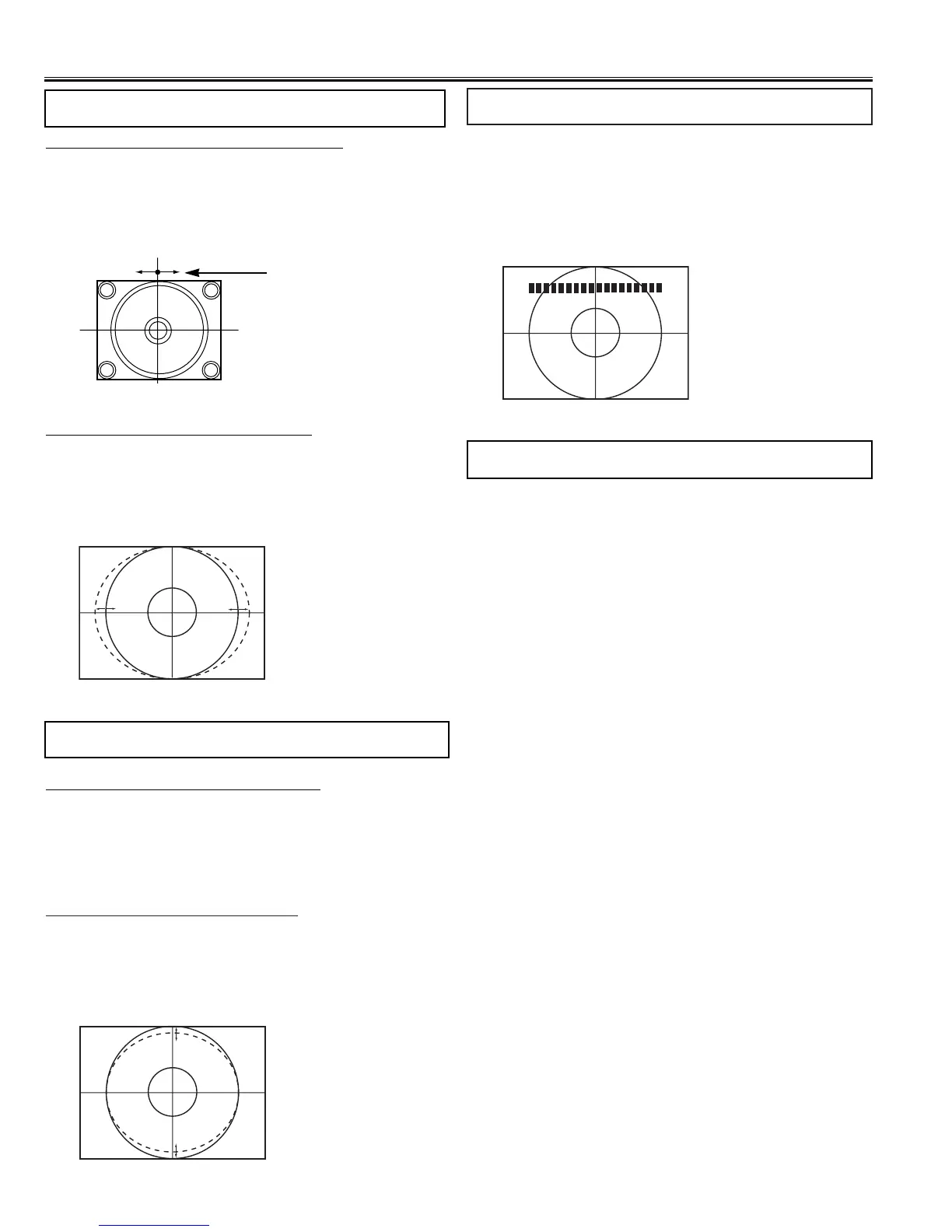
OSD POSITIONING ADJUSTMENT
(1) Receive circular pattern and set screen mode to “FULL”.
(2) Enter to the service mode and select mode “Regular”, and
select item No. 08 “Regular 08 OSD”. The OSD test bar will
appear on the top of screen.
(3) Press the Level up (+) or Level down (
-
) button to adjust
proper OSD positioning.
 Loading...