- 2 -
TUNER ADJUSTMENTS
Use a plastic screw driver for adjustments.
Adjust the intermediate frequency of AM to the frequency of ceramic filter.
Set of unit
Supply voltage
:
AC 230V
speaker impedance
:
4 ohms
standard output
:
50 mW
Function select:
:
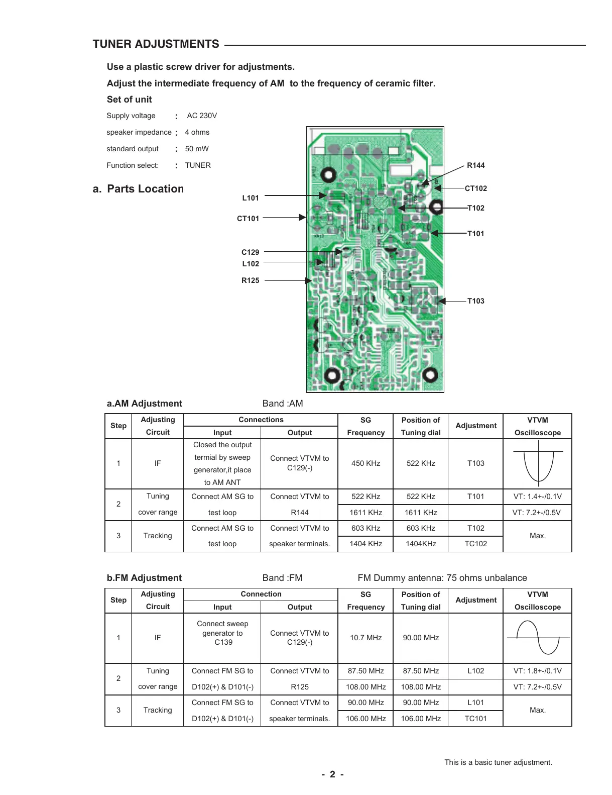
TUNER R144
a. Parts Locatio
L101
CT102
CT101
T102
T101
C129
L102
R125
T103
a.AM Adjustment
Band :AM
SG Position of VTVM
Input Output Frequency Tuning dial Oscilloscope
Closed the output
termial by sweep
generator,it place
to AM ANT
Connect AM SG to Connect VTVM to 522 KHz 522 KHz T101 VT: 1.4+-/0.1V
test loop R144 1611 KHz 1611 KHz VT: 7.2+-/0.5V
Connect AM SG to Connect VTVM to 603 KHz 603 KHz T102
test loop speaker terminals. 1404 KHz 1404KHz TC102
b.FM Adjustment
Band :FM FM Dummy antenna: 75 ohms unbalance
SG Position of VTVM
Input Output Frequency Tuning dial Oscilloscope
Connect FM SG to Connect VTVM to 87.50 MHz 87.50 MHz L102 VT: 1.8+-/0.1V
D102(+) & D101(-) R125 108.00 MHz 108.00 MHz VT: 7.2+-/0.5V
Connect FM SG to Connect VTVM to 90.00 MHz 90.00 MHz L101
D102(+) & D101(-) speaker terminals. 106.00 MHz 106.00 MHz TC101
3
2
3
Step
1
cover range
Adjusting
Circuit
2
1
Step Adjustment
IF T103
Tuning
522 KHz450 KHz
Connections
10.7 MHz
Adjusting Connection
Max.
Adjustment
Circuit
Tracking
Tracking Max.
Connect VTVM to
C129(-)
90.00 MHz
Tuning
cover range
IF
Connect sweep
generator to
C139
Connect VTVM to
C129(-)
This is a basic tuner adjustment.
 Loading...