Specifications
Power Rating . . . . . . . . . . . . . . . . . . . . . 120V, 60Hz
58W (Avg), 1.4A (Max)
Antenna Input Impedance. . . . . . . . . . . . . . . . . 75Ω
UHF/VHF/CATV
Receiving Channel . . . . . . . . . . . . . . . . 2 - 13 (VHF),
14 - 69 (UHF),
01, 14-94, 95-125 (CATV)
Remote Ready . . . . . . . . . . 24 Key Remote Control
Sound Output . . . . . . . . . . . . . . . . . . . . . . 1.0 W/CH
Intermediate Frequency
Picture IF Carrier. . . . . . . . . . . . . . . . . . 45.75MHz
Sound IF Carrier . . . . . . . . . . . . . . . . . . 41.25MHz
Color Sub Carrier . . . . . . . . . . . . . . . . . 42.17MHz
Picture Tube. . . . . . . . . . . . . . . . . . A48KRD82X(DT)
Semiconductors
Integrated Circuits. . . . . . . . . . . . . . . . . . . . . . . . 8
Transistors. . . . . . . . . . . . . . . . . . . . . . . . . . . . . 23
Except within Tuner and RC Pre-Amp.
Cabinet Dimensions
Width. . . . . . . . . . . . . . . . . . . . . . . . . . . . . 488mm
Height . . . . . . . . . . . . . . . . . . . . . . . . . . . . 452mm
Depth. . . . . . . . . . . . . . . . . . . . . . . . . . . . . 468mm
REFERENCE No. SM5110088-07
DS19500, G8FLM, PRODUCT CODE 111350180
AS
FILE NO.
SM5110088
REF : No.
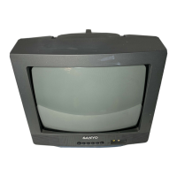
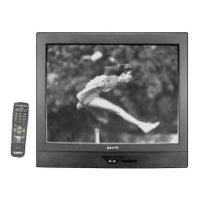
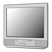
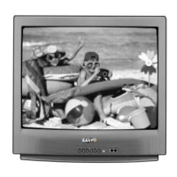
COLOR TELEVISION
Notice
CORRECTION
SERVICE FLASH
PRODUCTION CHANGE
ADD INFORMATION
Please add this notice to the Service Manual listed below.
REVISION 07
Category :
DS19500
Model:
U.S.A. / CANADA
Destination:
MAY / 15 / 2002
Date:
19500-07
Effective from : Chassis No.
NOTE: Match the Chassis No. on the unit’s back cover with the Chassis No. in the Service Manual.
If the Service Manual Chassis No. does not match the unit’s, additional Service Literature is
required. This chassis is similar to Chassis No. 19500-00, however, all Service Information is
given in this Notice for Chassis No. 19500-07 used in Model DS19500.
Contents
Safety Instructions . . . . . . . . . . . . . . . . . . 2
Service Adjustments. . . . . . . . . . . . . . 3 - 9
Purity and Convergence . . . . . . . . . 10 - 11
Service Hints. . . . . . . . . . . . . . . . . . . . . . 12
Mechanical Disassemblies. . . . . . . . . . . 13
Chassis Electrical Parts List . . . . . . 14 - 20
Cabinet Parts List . . . . . . . . . . . . . . . . . . 21
Component and Test Point
Locations . . . . . . . . . . . . . . . . . . . 22 - 24
Schematic Insert . . . . . . . . . . . . . . . 25 - 32
Schematic Notes . . . . . . . . . . . . . . . . . 25
Pin Layouts . . . . . . . . . . . . . . . . . . . . . 25
Capacitor and Resistor Codes . . . . . . 25
Block Diagram. . . . . . . . . . . . . . . 26 - 27
Voltage Charts . . . . . . . . . . . . . . . 26 - 28
Waveforms. . . . . . . . . . . . . . . . . . . . . . 28
Schematic Diagram . . . . . . . . . . . 29 - 32