Adjustment Instruction
1 Safety Instructions
1.1 Power supply must be cut off when replacing or welding any component or inserting / pulling out
connective lines;
1.2 Anti-electrostatic measures must be carried out during the whole producing processes!
a) Do not touch IC by hands at will;
b) Use anti-electrostatic iron;
c) Welder must wear anti-electrostatic glove;
1.3 Replacing any component with special safety requirement must refer to component list without
changing its specification and model at will.
2 Adjustment Equipments
Multimeter or oscilloscope
VG-849
CA-210
USB storage device
DVD ( HDMI 1.4 supported ) or equipments with the same functions
3 Adjustment Processes
3.1 Power voltage checking
According to the wiring diagram specified by “Product Specification”, connect power board
assembly, data processing assembly, IR/Key board assembly, backlight board assembly correctly,
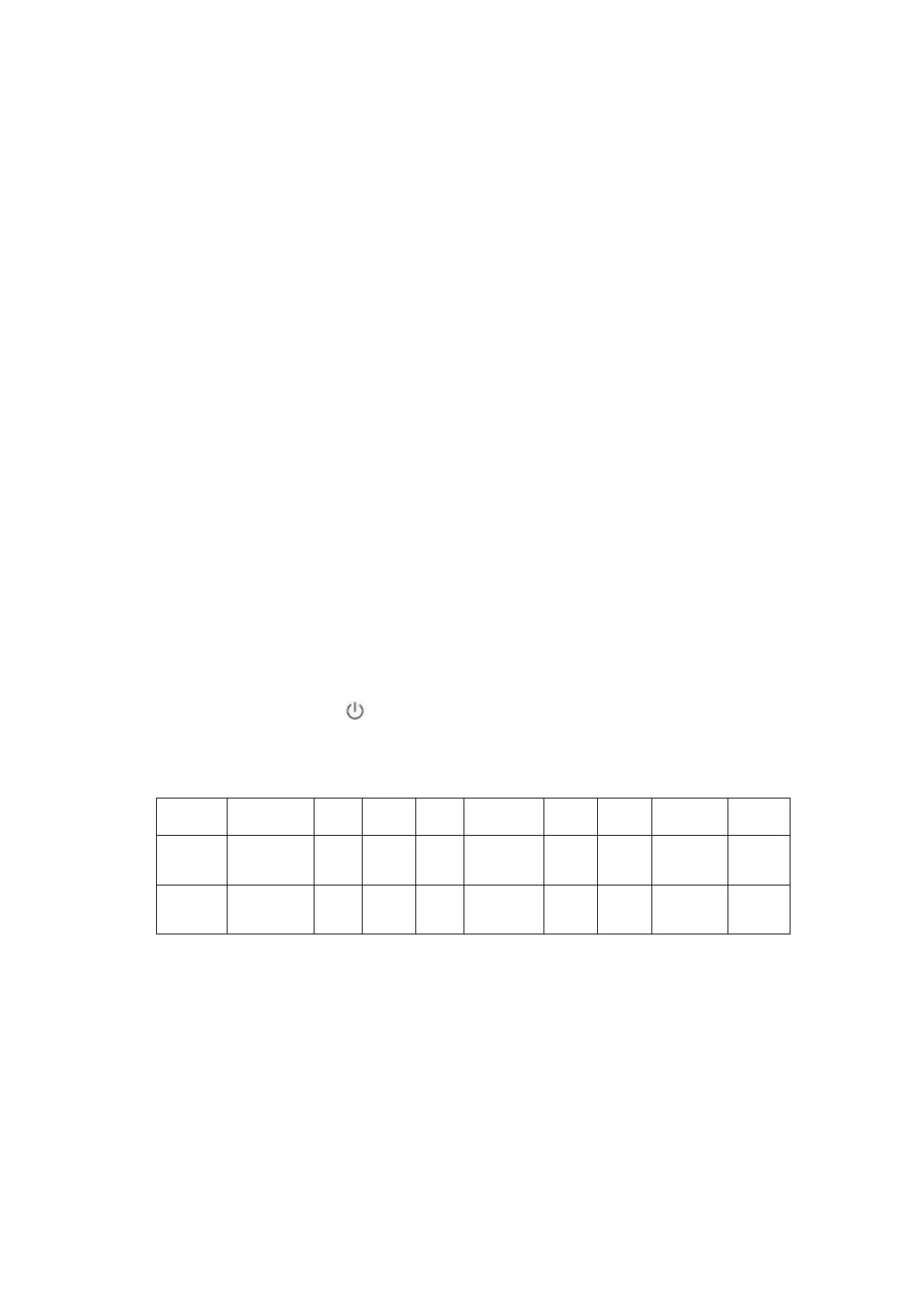
supply with power, press button
to power on the TV set.
Make sure the voltages of socket X601 each pin on the main board are correct.Voltage value
and range are listed as Table 1:
Table 1 Voltage of X601 each pin
X601 Pin1,2 3,4 5,6 7,8 9 10 11 12 13
Voltage 24V±5% 0
12
V±5%
0 ≤5.2V
5
V±5%
5
V±5%
≤5.2 V ≤5.2 V
Function AMP_PWR GND
+5V
STB
GND PWR_SW
Main
5V
+5V
STB
BL_PWM BL_ON
 Loading...